Quantcast
Channel: Network and Security Virtualization
Viewing all 481 articles
Browse latest View live

VMware Cloud on AWS with NSX: Connecting SDDCs Across Different AWS Regions

$
0
0

I prior shared this post on the LinkedIN publishing platform and my personal blog at HumairAhmed.com. In my prior blog post, I discussed how with VMware Cloud on AWS (VMC on AWS) customers get the best of both worlds for their move to a Software Defined Data Center (SDDC) – the leading compute, storage, and network virtualization stack for enterprises deployed on dedicated, elastic, bare-metal, and highly available AWS infrastructure. Another benefit of VMC on AWS, and the focus of this post, is that you can easily have a global footprint by deploying multiple VMC SDDCs in different regions.

As mentioned, in my prior post – today two AWS regions are available, US West (Oregon) and US East (N. Virginia) with more regions planned for the near future. By clicking a button and deploying SDDCs in different regions, you can easily have a global SDDC infrastructure backed by all the vSphere, vSAN, and NSX functionality you love.

Below you can see I’ve already linked my VMC to my AWS account as explained in my prior post and deployed two SDDCs both inherently running vSphere, vSAN, and NSX. One SDDC is deployed in the AWS US West (Oregon) region and the other is deployed in the US East (N. Virginia) region.

Figure 1: VMC on AWS: Two SDDCs Deployed in Different Regions

Figure 1: VMC on AWS: Two SDDCs Deployed in Different Regions


Below is my lab setup within VMC and respective connectivity to my on-prem lab. I’ve connected the two SDDCs in VMC via IPSEC VPN. My SDDC deployed in the AWS US West (Oregon) region is also connected via IPSEC VPN to my on-prem environment in Palo Alto, CA.

It’s important to note here all the networking capabilities within VMC, including IPSEC VPN used here, is provided by NSX. The workloads in VMC sit on NSX logical networks, the NSX DLR is used for east/west distributed routing, and the NSX Edge can be used to provide North/South capabilities out the AWS Internet Gateway and also for edge services like firewall, NAT, VPN, etc. Below, I’m leveraging IPSEC VPN on the NSX Edge to connect to another SDDC in another region and also to connect to my local on-prem environment.

Figure 2: VMC Lab Setup

Figure 2: VMC Lab Setup


At AWS re:Invent 2017 new capabilities of L2VPN and AWS Direct Connect were also announced. These new capabilities provide for additional use cases and capabilities such as high-speed private network connectivity from on-prem directly to VMC, stretched network support, and faster cold and live application migration capabilities. I will leave these to discuss for a follow-up post.

Below you can see the logical networks I’ve created in the VMC SDDCs in both the US West (Oregon) and US East (N. Virginia) regions respectively.

Figure 3: NSX Logical Networks in VMC SDDC in the US West (Oregon) Region

Figure 3: NSX Logical Networks in VMC SDDC in the US West (Oregon) Region

Figure 4: NSX Logical Networks in VMC SDDC in the US East (N. Virgina) Region

Figure 4: NSX Logical Networks in VMC SDDC in the US East (N. Virgina) Region


In the below Compute Gateway (CGW) IPSEC VPN configuration for both SDDCs, you can see I am exposing the VMC_App network between the SDDCs. From above logical networks, you can see the VMC_App network in the SDDC in the US West (Oregon) region has a subnet of “10. 61. 4. 16/28” and the VMC_App network in the SDDC in the US East (N. Virginia) region has a subnet of “10. 71. 4. 16/28” VMs/workloads on these networks can communicate to each other across SDDCs via policy-based IPSEC VPN configuration and respective security policies shown further below.

Note, the SDDC in the US West (Oregon) region is also connected to the local data center in Palo Alto, CA via another IPSEC VPN configuration. In this configuration the VMC_Web network is exposed as there are some on-prem workloads that need to communicate to the Web VMs in the VMC SDDC in the US West (Oregon) region.


SDDC in US West (Oregon)

Figure 5: SDDC in US West (Oregon))

Figure 5: SDDC in US West (Oregon))


Figure 6: IPSEC VPN Configuration of SDDC in the US West (Oregon) Region

Figure 6: IPSEC VPN Configuration of SDDC in the US West (Oregon) Region


SDDC in US East (N. Virginia)

Figure 7: SDDC in US East (N. Virginia)

Figure 7: SDDC in US East (N. Virginia)


Figure 8: IPSEC VPN Configuration of SDDC in the US East (N. Virginia) Region

Figure 8: IPSEC VPN Configuration of SDDC in the US East (N. Virginia) Region


The respective security policies in my VMC lab environment allow for ICMP communication between the respective workloads between VMC SDDCs and also ICMP communication from on-prem workloads; this configuration is shown below.

Figure 9: SDDC in US West (Oregon): CGW Firewall Rules

Figure 9: SDDC in US West (Oregon): CGW Firewall Rules


Figure 10: SDDC in US East (N. Virginia): CGW Firewall Rules

Figure 10: SDDC in US East (N. Virginia): CGW Firewall Rules


Below are two App VMs on the VMC_App NSX logical network at both regions respectively. The VM in the SDDC in the US West (Oregon) region has an IP address of “10. 61. 4. 17” and the VM in the SDDC in the US East (N. Virginia) region has an IP address of “10. 71. 4. 17“.

Figure 11: SDDC in US West (Oregon): App VM on 'VMC_App' NSX Logical Network

Figure 11: SDDC in US West (Oregon): App VM on ‘VMC_App’ NSX Logical Network


Figure 12: SDDC in US East (N. Virginia): App VM on 'VMC_App' NSX Logical Network

Figure 12: SDDC in US East (N. Virginia): App VM on ‘VMC_App’ NSX Logical Network


Below you can see the App VMs in the different VMC SDDCs and respective AWS Regions can communicate with each other.

Figure 13: SDDC in US West (Oregon): App VM Pinging App VM in Other SDDC and Region

Figure 13: SDDC in US West (Oregon): App VM Pinging App VM in Other SDDC and Region


Fifure 14: SDDC in US East (N. Virginia): App VM Pinging App VM in Other SDDC and Region

Fifure 14: SDDC in US East (N. Virginia): App VM Pinging App VM in Other SDDC and Region


Additionally, per my VMC lab configuration shown further above, my local workload on-prem in Palo Alto, CA with an IP address of “10. 114. 223. 70” can communicate to my Web VM with IP address of “10. 61. 4. 1” in the SDDC in the US West (Oregon) region.

Figure 15: SDDC in US West (Oregon): Web VM on 'VMC_Web' NSX Logical Network

Figure 15: SDDC in US West (Oregon): Web VM on ‘VMC_Web’ NSX Logical Network


Figure 16: Communication Between On-prem VM and Web VM in the SDDC in the US West (Oregon) Region

Figure 16: Communication Between On-prem VM and Web VM in the SDDC in the US West (Oregon) Region


As you can see, with VMC on AWS, you can easily have a global footprint by deploying multiple VMC SDDCs in different regions. Connectivity is possible between SDDCs in different regions and also to an on-prem environment.

For more information on VMC on AWS, and how to get started check-out my prior post and the VMC on AWS Documentation page.


The post VMware Cloud on AWS with NSX: Connecting SDDCs Across Different AWS Regions appeared first on Network Virtualization.


VMware AppDefense & CB Defense Demo

$
0
0

As you may have heard, VMware and Carbon Black have come together to deliver best-in-class security architected for today’s data centers.

In this demo, you’ll see an example of how CB Defense and VMware AppDefense combine to enforce known good application behavior and detect threats using industry leading detection and response technology.

For this demo, we’ll show how an advanced security breach can come in under the guise of an innocuous application (Powershell) and often go undetected.  We’ll walk through the steps that security teams can now take to respond and address the attack all in one application.


The post VMware AppDefense & CB Defense Demo appeared first on Network Virtualization.

Fortinet FortiGate-VMX and NSX use cases

$
0
0

NSX is an extensible platform; other vendors security solutions can be added to it by means of the Northbound REST API, and two private APIs: NETX for network introspection, and EPSEC for guest introspection.

Fortinet’s FortiGate-VMX solution uses the NSX NETX API to provide advanced layer 4-7 services via service insertion, also called service chaining.  This enables the additional inspection of VM traffic prior to that traffic reaching the vSwitch.  This enhances micro-segmentation where there is need for greater application recognition, anti-malware, and other Next Generation Firewall features.  The scale-out nature of NSX is maintained as NSX handles the instantiation of FortiGate service VMs on the hosts within the deployed cluster retaining its operational advantages, if the cluster grows additional FortiGate-VMX service machines will be created as needed.


One of the primary advantages to FortiGate-VMX is the availability of VDOMs for multi-tenancy in a service provider or enterprise environment – this enables segmenting traffic by organization, business group, or other construct in addition to application.  The segregation includes the administration, VDOMs are managed independently of one another, this can also be used to split the different security functions such as anti-virus, IPS, and application control into isolated units or only use certain features against specific groups.  For example a PCI group might have more features enabled, but be lower throughput.  Each VDOM has its own NSX Service Profile, which means the traffic steering policy can be tailored precisely for the domain.

NSX with FortiGate-VMX unites the depth of the Fortinet solution with the scale-out orchestration and automation capabilities of NSX. This ensures that new workloads are protected by policy while making data center security management and operations simpler and more efficient.  The white paper provides more information on the solution features and use cases that these can be applied to:

White Paper – Fortinet VMX with VMware NSX

The post Fortinet FortiGate-VMX and NSX use cases appeared first on Network Virtualization.

Getting More Out Of NSX Webcast Series

$
0
0


Each episode in this Getting More Out of NSX webcast series has its own topic, so there is no need to watch each episode to understand the next one. The episodes cover a variety of NSX features and explain in detail how NSX is the solution to key challenges faced by IT professionals. With the use of product demos, our NSX experts will show you how NSX allows granular control on an application by application basis to achieve the dream of universal security across the network. You will learn about:

  • NSX optimization for performance – how NSX eliminates the need for agent management and overprovisioning, thus reducing costs
  • NSX automated ubiquitous deployment & enforcement
  • NSX simplified policy management & automation across services


Now Available On-Demand

Episode 1: Deep Dive into NSX Service Composer, covered the mapping of applications, adding context to your Security Policy, and the NSX Service Composer and Application Rule Manager. Episode 2: Micro-segmentation Preparation and Planning with vRNI, covered how to perform Plan Security around Applications, build rulesets from Recommendations from vRNI, and verify rules compliance.

There is no need to watch Episodes 1 and 2 to understand Episodes 3 and 4 as each episode has its own topic. Episodes 1 and 2 can be accessed here.


Upcoming

Episode 3: NSX Micro-segmentation PCI using vRNI

Webcast Date:

January 11th, 2018 11am PST

Presenter:

Mason Ferratt, Sr. Systems Engineer, Network & Security Business Unit, VMware

Do you have a hard time visualizing PCI compliance of your datacenter? Are you using NSX for micro-segmentation? In this session, we will focus on VMware NSX as a framework protecting PCI assets in your VMware environment. Then we use vRealize Network Insight (vRNI) to provide the visualization and monitoring of those assets to validate compliance to specific PCI objectives.

In this installment of the Getting More Out Of NSX series, we will focus on how we can use vRNI to assess compliance for an NSX environment. You will learn:

  • How to use the PCI dashboard to identify PCI objective compliance relating to networking and security
  • How to ascertain the status of VMs, NSX security group associations, and firewall rules as well as relevant flows
  • How to save PCI specific searches and pin them

Register now for this webcast series


Episode 4: Application Rule Manager (ARM) – Fastest Security Groups & Firewall Rules Creation

Webcast Date:

January 18th, 2018 11am PST

Presenter:

Kevin Fletcher, Sr. Systems Engineer, VMware

Enforcing a whitelisted application policy, where zero trust architecture is the default, is the goal for most of us. However, getting even a single workflow identified and a ruleset created for it can be a real challenge. How do you get started? In this session, we will look at the built-in tool that VMware NSX provides to help simplify the process of micro-segmentation workflows by evaluating current applications and creating a whitelisted rule base for you to enforce. It is the easy button! The tool is called Application Rule Manager (ARM) and was introduced in VMware NSX version 6.3. ARM correlates specific user-defined and real-time flow information between a workload, so a security model can be built around it without making compromises or adding complexity in defining the actual communication. This quick targeted modeling of an application significantly reduced time to value and enables you to begin enforcing a whitelist policy in your data centers.

In this instalment of the Getting More Out Of NSX series, we will explore the ease of use to provide targeted modeling of an application based on live flows and the ability to apply specific rules to enable micro-segmentation. You will learn:

  • How to quickly identify real-time granular application flows
  • How to use flow tables to create security groups, IP sets, services and firewall rules
  • How to add context to your security policies

Register now for this webcast series


The post Getting More Out Of NSX Webcast Series appeared first on Network Virtualization.

VMware Cloud on AWS with NSX: Communicating with Native AWS Resources

$
0
0

If you haven’t already, please read my prior two blogs on VMware Cloud on AWS: VMware SDDC with NSX Expands to AWS and VMware Cloud on AWS with NSX – Connecting SDDCs Across Different AWS Regions; also posted on my personal blog at humairahmed.com. The prior blogs provide a good intro and information of some of the functionality and advantages of the service. In this blog post I expand the discussion to the advantages of VMware Cloud on AWS being able to communicate with native AWS resources. This is something that would be desired if you have native AWS EC2 instances you want VMware Cloud on AWS workloads to communicate with or if you want to leverage other native AWS services like AWS S3 VPC Endpoint or RDS.

From my prior blogs you know that with VMware Cloud on AWS customers get the best of both worlds for their move to a Software Defined Data Center (SDDC) – the leading compute, storage, and network virtualization stack for enterprises deployed on dedicated, elastic, bare-metal, and highly available AWS infrastructure. And yes, as discussed in my last post, customers can easily have a global footprint by deploying multiple SDDCs in different regions. But what if customers need access to native resources on AWS? VMware Cloud on AWS provides a benefit here as well.

VMware Cloud on AWS is born from a strategic partnership between VMware and Amazon; as such, both have worked together to develop functionality that allows for native access to AWS resources. When customers login and click the Create SDDC button as shown below, the first step is linking to an AWS account. This linking process is important to understand as it enables permissions and access for internal communication between VMware Cloud on AWS and native AWS resources.

Figure 1: Create SDDC on VMware Cloud on AWS

Figure 1: Create SDDC on VMware Cloud on AWS


AWS has a service called CloudFormation which simplifies provisioning and management on AWS. It allows the creation of templates for service/application architectures you want. AWS CloudFormation uses these templates for quick and reliable provisioning of the services or applications, which are called stacks.

VMware Cloud on AWS leverages CloudFormation templates where its own VMware stack is leveraged. To connect/link VMware Cloud on AWS to an existing or new AWS account you own, you simply need to log into your AWS account, and click the below OPEN AWS CONSOLE WITH CLOUDFORMATION TEMPLATE button within VMware Cloud on AWS as shown below.

Figure 2: VMware Cloud on AWS - Using CloudFormation Template

Figure 2: VMware Cloud on AWS – Using CloudFormation Template


In AWS, you will need to acknowledge changes to AWS account and grant permissions as shown below.

Figure 3: Approval Required for CloudFormation Template

Figure 3: Approval Required for CloudFormation Template


What’s happening here is that you’re giving VMware Cloud on AWS permission to discover resources like VPCs and respective subnets. Also, appropriate policies and roles are being applied so the VMware Cloud on AWS account instance can connect into your VPC. This is a one-time operation that needs to be executed as part of the provisioning process.

Another important thing that occurs here during the linking process is that AWS Elastic Network Interfaces (ENIs) are created within the AWS customer VPC and used by VMware Cloud on AWS. A screenshot of these ENIs created in the AWS customer VPC is shown below.

An ENI is used to communicate to the NSX logical network subnets in VMware Cloud on AWS. This ENI will also be listed within the respective VPC subnet’s route table to direct traffic directly to VMware Cloud on AWS; no traffic is sent over the AWS Internet Gateway (IGW) thus providing for more efficient and high bandwidth access between the AWS customer VPC and VMware Cloud on AWS. Customers also realize savings as compared to having to do VPC Peering or utilizing IGW where transit charges can be incurred. This is an incredibly cool and useful capability which highlights the joint collaboration of VMware and Amazon. It’s important to ensure you never delete these ENIs.

Figure 4: ENIs Created for VMware Cloud on AWS in the AWS Customer VPC via the CloudFormation Template

Figure 4: ENIs Created for VMware Cloud on AWS in the AWS Customer VPC via the CloudFormation Template


In the below screenshot of my respective subnet route table in AWS where my native EC2 workloads reside, you can see the ENI (eni-e753b5d) used to reach my NSX logical network subnets (10.16.4.X/28) in VMware Cloud on AWS. You can see a default route to the AWS IGW also exists. An AWS IGW and respective route will exist by default in the default VPC and route table; if using a non-default VPC, an AWS IGW and respective route is not present by default, but can be added if desired. In this example/post IGW will not be utilized.

Figure 5: Respective Subnet Route Table in AWS

Figure 5: Respective Subnet Route Table in AWS


Below is the diagram of my setup. You can see VMware Cloud on AWS has direct connectivity to AWS resources through the AWS network via ENI.

Figure 6: VMware Cloud on AWS Lab Setup

Figure 6: VMware Cloud on AWS Lab Setup


A few important things to note about the above diagram and AWS/VMware Cloud on AWS environment:

  • the security policies in VMware Cloud on AWS are on the CGW Edge firewall and must allow traffic for respective native AWS workloads you want to be able to communicate with in the AWS customer VPC
  • the security group and ACL security policies in the AWS customer VPC must allow traffic for respective workloads you want to be able to communicate with in VMware Cloud on AWS
  • every AWS VPC has a default security group and network ACL
  • the network ACL default policy in a VPC allows all traffic inbound and outbound
  • the default security group policy in a VPC allows all traffic from inbound to the default security group; outbound traffic on the default security group allows all traffic
  • in AWS customer VPC, if there is no IGW/route to IGW or public IP, there can be no communication via Internet; IGW is not needed for AWS VPC Connectivity using ENI
  • the ENIs used for AWS VPC connectivity between the AWS customer VPC and VMword Cloud on AWS are members of the default security group; it’s important not to change the default rules to where the AWS VPC connectivity using the respective ENIs is blocked


Below is the diagram from my VMware Cloud on AWS environment. You can see at the bottom right of the diagram that connectivity is established to my AWS VPC where my native EC2 workloads reside. The Amazon VPC icon in this diagram represents the left part of the lab diagram above labeled Native AWS.

Figure 7: Diagram from VMware Cloud on AWS

Figure 7: Diagram from VMware Cloud on AWS


Below, you can see I have deployed two EC2 instances in AWS; this is also reflected in the lab diagram above, Both instances have only private IP addresses. The EC2 instance on the top has an IP address of 172. 31. 25. 164. The EC2 instance below it has an IP address of 172. 31. 25. 154.

Figure 8: AWS EC2 Instance with Private IP Address of "172. 31. 25. 164"

Figure 8: AWS EC2 Instance with Private IP Address of “172. 31. 25. 164”


Figure 9: AWS EC2 Instance with Private IP Address of "172. 31. 25. 154"

Figure 9: AWS EC2 Instance with Private IP Address of “172. 31. 25. 154”


You can see from the above, both EC2 instances have been placed in a custom security group titled Web Servers.

I will ping the EC2 instances in my Web Servers security group from my App VM on my App NSX logical switch in VMware Cloud on AWS. I also have a web server running on my EC2 instance with IP address of 172. 31. 25. 154. Accordingly, I allow both HTTP, SSH, and ICMP traffic to my EC2 instances in the Web Servers security group as shown below. Note, I only edit the inbound rules here, and leave the outbound as default.

In AWS, network ACLs are stateless while security group policies are stateful. When you define an ACL security policy allowing specific traffic in, you also have to define an ACL security policy going out. Security groups behave differently, since they are stateful. When you define a security policy allowing specific traffic in, by default the respective return traffic will be allowed out.

Figure 10: Inbound Rules for "Web Servers" Security Group

Figure 10: Inbound Rules for “Web Servers” Security Group


Figure 11: Outbound Rules for "Web Servers" Security Group

Figure 11: Outbound Rules for “Web Servers” Security Group


Since I will also show an EC2 instance pinging the App VM in VMware Cloud on AWS, I also have to edit the inbound policy for the security group my ENIs are in to allow traffic from my Web Servers security group. The reason for this is, as mentioned prior and shown in the respective AWS customer VPC subnet route table, the created ENIs are used for communicating to the networks in VMware Cloud on AWS. Similar to prior example, I leave the outbound as default.

Figure 12: Inbound Rules for Default Security Group

Figure 12: Inbound Rules for Default Security Group


Figure 13: Outbound Rules for Default Security Group

Figure 13: Outbound Rules for Default Security Group


I also insure the respective traffic is allowed through the VMware Cloud on AWS CGW firewall as shown below. The first four rules allow for HTTP, ICMP, and SSH traffic; the policies are consistent with those I created in AWS to allow successful communication between native AWS resources and VMware Cloud on AWS workloads. There is a default Default Deny All as the last firewall rule (not shown below).

Figure 14: VMware Cloud on AWS CGW Firewall Rules

Figure 14: VMware Cloud on AWS CGW Firewall Rules


You can see from below screen shots, from my App VM (10.61.4.17) on my App NSX logical network in VMware on Cloud on AWS, I can ping both EC2 instances (172. 31. 25. 154 and 172. 31. 25. 164) in AWS VPC. I can also ping from the EC2 instances to my App VM in VMware Cloud on AWS.


From VM in VMware Cloud on AWS to EC2 Instances in AWS VPC:

Figure 15: Successful Ping From VM in VMware Cloud on AWS to EC2 Instances in AWS VPC

Figure 15: Successful Ping From VM in VMware Cloud on AWS to EC2 Instances in AWS VPC


From EC2 Instance in AWS VPC to VM in VMware Cloud on AWS:

Figure 16: Successful Ping From EC2 Instance in AWS VPC to VM in VMware Cloud on AWS

Figure 16: Successful Ping From EC2 Instance in AWS VPC to VM in VMware Cloud on AWS


Below, traceroute from the App VM (10.61.4.17) in VMware on Cloud on AWS to the Web EC2 instance in AWS (172.31.25.154) shows the path from the App VM to the NSX DLR (10.61.4.30) to CGW Edge (169.254.3.1) and directly out the CGW host to the destination EC2 instance (172.31.25.154).

Figure 17: Traceroute from the App VM in VMware Cloud on AWS to the Web EC2 Instance in AWS

Figure 17: Traceroute from the App VM in VMware Cloud on AWS to the Web EC2 Instance in AWS


As expected, and based on my security policies, from my App VM, I can also access the web server on the EC2 host via http as shown below.

Figure 18: Accessing the Web Server on the EC2 Host from App VM in VMware Cloud on AWS via HTTP

Figure 18: Accessing the Web Server on the EC2 Host from App VM in VMware Cloud on AWS via HTTP


Similar to communicating with AWS EC2 instances, using the same communication channel via direct high bandwidth connectivity, VMware Cloud on AWS can natively access and utilize additional services like AWS S3 VPC Endpoint and RDS. The ability to directly access these native services from VMware Cloud on AWS opens the door for many additional use cases and benefits; these additional examples and use cases will be covered in a follow-up post.

For more information on VMware Cloud on AWS, and how to get started check-out the below links.

The post VMware Cloud on AWS with NSX: Communicating with Native AWS Resources appeared first on Network Virtualization.

“Building NSX Powered Clouds and Data Centers for SMBs” is available now

$
0
0

I am honored and humbled to announce my new book “Building NSX Powered Clouds and Data Centers for Small and Medium Businesses”.


Building VMware NSX Powered Clouds and DCs for SMB Book Cover Page


This is a concise book that provides step by step information to design and deploy NSX in Small and Medium size data centers. My aim for writing this book is to give architects and engineers the necessary tools and techniques to transform their data center from legacy architecture to software defined (SDN) architecture. The SDN architecture is the foundation to build the private cloud.

The book has about 90 pages covering following topics:

  • NSX and SMB data center introduction
  • Important vSphere design considerations
  • vSphere cluster design and NSX deployment models
  • NSX individual component design and deployment considerations
  • NSX Operations: monitoring and troubleshooting
  • Growing NSX deployments

Many technology vendors tend to focus efforts in the large data center space, the fact remains that the small/medium business (SMB) space represents a substantial part of the IT marketplace.

The book is available to purchase from NSX Store.
Electronic version of the book can be downloaded from here.

The post “Building NSX Powered Clouds and Data Centers for SMBs” is available now appeared first on Network Virtualization.

Enhancing NSX with Check Point vSEC

$
0
0

While VMware NSX enables micro-segmentation of the Software Defined Data Center, it mostly polices traffic in layers 3 and 4, with only limited application level (layer 7) support.  Sometimes additional layers of protection are needed for use cases such as Secure DMZ or meeting regulatory compliance requirements like PCI, in which case partner solutions can be added to the platform, with traffic steered into the supplemental solution prior to reaching the vSwitch (virtual wire).  The resulting combination is high throughput due to the scale-out nature of NSX, but can also provide deep traffic analysis from the partner solution.

The usual enemy of deep traffic inspection in the data center is bandwidth.  NSX addresses this issue, micro-segmentation security policy is zero trust – only traffic explicitly permitted out of a VM can pass, then steering policy to 3rd party solutions can be designed in order that bulk protocols such as storage and backup bypass them, leaving a more manageable amount of traffic for Check Point vSEC to provide IPS, anti-virus and anti-malware protection on, including Check Point’s Sandblast Zero-Day Protection against zero day attacks.

The connection between vSEC and NSX enables dynamic threat tagging, where traffic from an VM reaches a vSEC gateway, in addition to denying the traffic the VM can be tagged as infected.  This tag can then be used to trigger a remediation workflow, putting the VM into quarantine, so the NSX distributed firewall can block all traffic from it (perhaps except for anti-virus updates and patches that may be required to remediate), alerting an administrator, taking a snapshot for later analysis etc.

This enhancement of the native capabilities of NSX demonstrates the power of the platform and its ability to use best of breed point security solutions to increase visibility of and protection against threats.  Dynamic response to malicious traffic with the ability to change the applied security policy on the fly is a major benefit to NSX and the software defined datacenter.

For more details on use cases of vSEC with NSX please see our white paper, –  VMware NSX with Check Point vSEC

The post Enhancing NSX with Check Point vSEC appeared first on Network Virtualization.

VMware NSX Micro-segmentation – Horizon 7

$
0
0

Organizations that embark on the journey of building our virtual desktop environments, are taking traditionally external endpoints and bringing them into the data center.  These endpoints are now closer and most times, reside on the same networking infrastructure as the backend application servers that they may access. These endpoints run Windows or even Linux desktop operating systems with multiple end-users that can access them. Malicious attacks that would traditionally take place outside the data center should an end-user find their desktop or laptop machine infected, could now take place on their virtual desktops inside the data center.  With physical equipment, it’s easy to isolate the physical desktop or laptop and remediate the attack.  Securing virtual desktop environments requires a different approach, but not one that’s unattainable.  Securing an end user computing deployments is one of the primary security use cases for VMware NSX and can help provide a layered approach to securing virtual desktop workloads in the data center.

The NSX platform covers several business cases for securing an end user computing deployment.  Each of these use cases, helps provide a multi-layered approach to ensure end user endpoints are as secure as possible in the data center.

Figure 1 – NSX Security Services for End User Computing Use Cases

Figure 2 – NSX Security Services for End User Computing Use Cases cont.

As we revise the Horizon reference architecture for Horizon 7 as well as the NSX for EUC Design Guide, we’ll be bringing NSX reference architecture decisions into the Horizon 7 architecture to help provide guidance for customers building end user computing environments.  Over the next several months, the Horizon 7 reference architecture document will continue to evolve adding more and more NSX features into it including Load Balancing, RDSH, Guest Introspection, and Identity Firewall.  There are several enhancements currently and even more coming that will be simplifying NSX deployment with Horizon.

With the latest revision of the Horizon 7 reference architecture, we’re providing guidance around how to secure the East-West traffic within the Horizon deployment.  This guidance is all encompassing of an entire Horizon 7 deployment.

Figure 3 – NSX and Horizon Logical Components

Securing East-West traffic between desktop systems is an easy security model to put in place using NSX.  However, the VDI desktops or the RDSH systems are not the only systems that comprise a Horizon deployment.  There are several Horizon management components that provide the facilities to create and spin up those VDI and RDSH systems.  Each of these components communicates over specific ports and protocols.  These are outlined in the Horizon 7 Network Ports document.  Using the same methodologies for securing VDI and RDSH systems, NSX can provide the same level of micro-segmentation around the Horizon management components.

As part of the process to integrate NSX into the Horizon Reference Architecture, each of the communication ports and protocols were laid out into two separate PowerShell scripts using PowerNSX, to allow customers the ability to insert all the necessary NSX Distributed Firewall rules, Security Groups, and Services into the NSX Manager.

Below is an example output from the script and how the rules and the associated NSX Security Groups and Services would look in the NSX Manager:

Table 1 Horizon 7 Desktops – VDI or RDS Host


Table 2 Horizon 7 Desktops – VDI or RDS Host Services

The services listed below are the breakdowns of each port and protocol specific to the service referenced in the previous table.

For the next part of the series, we will be considering how NSX and RDSH servers can be secured as well as discussion on Load Balancing Horizon with NSX. NSX has several business cases for end user computing deployments.  Securing the VDI and RDSH systems along with the Horizon management infrastructure components, provides the most in-depth micro-segmentation policy for Horizon deployments.  The script referenced in this post can be downloaded here.  The script is not maintained or supported by VMware at this time.  It is meant more as a guide and quick start to micro-segmenting a Horizon deployment.  Please treat this as such when testing.  For full details of the script referenced, head over to the NSX for EUC Design Guide.

The post VMware NSX Micro-segmentation – Horizon 7 appeared first on Network Virtualization.


NSX-T: Routing where you need it (Part 2, North-South Routing)

$
0
0

In the first part of this blog series, NSX-T: Routing where you need it (Part 1), I discussed how East-West (E-W) routing is completely distributed on NSX-T and how routing is done by the Distributed Router (DR) running as a kernel module in each hypervisor. 

In this post, I will explain how North-South (N-S) routing is done in NSX-T and we will also look at the ECMP topologies. This N-S routing is provided by the centralized component of logical router, also known as Service Router. Before we get into the N-S routing or packet walk, let’s define Service Router.

Service Router (SR)

Whenever a service which cannot be distributed is enabled on a Logical Router, a Service Router (SR) is instantiated. There are some services today on NSX-T which are not distributed such as:

1) Connectivity to physical infrastructure
2) NAT
3) DHCP server
4) MetaData Proxy
5) Edge Firewall
6) Load Balancer

Let’s take a look at one of these services (connectivity to physical devices) and see why a centralized routing component makes sense for running this service. Connectivity to physical topology is intended to exchange routing information from NSX domain to external networks (DC, Campus or WAN). In a datacenter leaf and spine topology or any other datacenter topology, there are designated devices that peer with WAN routers to exchange routes in BGP and provide N-S connectivity. To avoid exponential growth of BGP peerings from each hypervisor and reduce complexity of control plane, a dedicated routing component (Service Router) is designed to serve the need.

NSX-T achieves best of both worlds with DR/SR approach, distributed routing (in kernel) for E-W traffic, centralized routing for N-S traffic and other centralized services.

Introducing the Edge node:

We need a centralized pool of capacity to run these services in a highly-available and scale-up fashion. These appliances where the centralized services or “SR Instances” are hosted are called Edge nodes. They are available in two form factors: Bare Metal or VM(both leveraging Linux Foundation’s DPDK Technology).

So, when a logical router is connected to physical infrastructure, a SR is instantiated on the edge node. Similarly, when a centralized service like NAT is configured on logical router, a SR or service instance for that particular logical router is instantiated on the Edge node. Edge nodes (all VM or all Baremetal) can be logically grouped into an Edge cluster to provide scale out, redundant, and high-throughput gateway functionality for logical networks.

The following diagram shows a typical leaf and spine topology with Edge nodes providing connectivity to the physical infrastructure. As shown in the diagram, Distributed Router (DR) component of a Logical router is instantiated on all the transport nodes (Compute hypervisors and Edge nodes). To provide connectivity to the physical infrastructure, SR has been instantiated on the Edge nodes. These Edge nodes are also configured as Transport nodes and are assigned a TEP (Tunnel End Point) IP just like compute hypervisors to send/receive overlay traffic to/from compute hypervisors.  As shown in the diagram below, traffic from a VM hosted on a compute hypervisor goes through the Edge node on a overlay network, to connect to a device in physical infrastructure.

Figure 1: Physical Topology showing Compute hypervisors and Edge Node

Before we get into a detailed packet walk for this N-S traffic, it is imperative to understand the architecture details as to how the two routing components (DR and SR) are connected.

As soon as a logical router is configured via NSX-T manager, a DR is instantiated in all transport nodes. When we enable a centralized service on that logical router, a SR is instantiated. An internal link called Intra-Tier Transit link is auto created using a Transit Logical switch between DR and SR. This link defaults to an IP address in 169.254.0.0/28 subnet. Neither you have to configure this transit logical switch nor configure IP addressing on the link (unless, user wants to change the subnet range) nor configure any routing between DR and SR. All of this is auto plumbed, meaning that we take care of this in background.

Moving on, let’s take a look at the interfaces and how we are taking care of this routing in background. Following is the logical view of a Logical router showing both DR and SR components when connected to a physical router

Figure 2: Logical Topology showing Logical router components (DR & SR)

As shown in the diagram above, following are the interfaces on the logical router.

  • Uplink:  Interface connecting to the physical infrastructure/router. Static routing and EBGP are supported on this interface. Both static routing and EBGP can leverage BFD.
  • Downlink:  Interface connecting to a logical switch.
  • Intra-Tier Transit Link: Internal link between the DR and SR, using a transit logical switch.

The following output from an Edge node shows both components of a logical router, DR and SR. Observe the Intra-Tier Transit link on DR with an IP of 169.254.0.1 and on SR with an IP of 169.254.0.2.

Figure 3: DR/SR interfaces

Routing between SR and DR

Let’s look at how routing works between DR and SR. We are not running any routing protocol on the Intra-Tier transit link. As soon as SR is instantiated, Management plane configures a default route on DR with the next hop IP address of SR’s Intra-Tier transit link IP, which is 169.254.0.2 in this case.

This allows the DR to take care of E-W routing while the SR provides N-S connectivity to all the subnets connected to the DR.

The following output from ESXi host, DR shows the default route with a gateway or next hop IP of SR, 169.254.0.2.

Figure 4: DR Routing table showing default route to SR

Management plane also creates routes on SR for the subnets connected to DR, with a next hop IP of DR’s Intra-Tier transit link, which is 169.254.0.1 in this case.

These routes are seen as “NSX Connected” routes on SR. The following output from Edge node shows the routing table of SR. Observe that 172.16.10.0/24 is seen as NSX connected route with DR as next hop, 169.254.0.1.

Figure 5: SR Routing table

Let’s take a look at this N-S traffic flow in detail. In the following topology, I have a Web VM hosted on a ESXi hypervisor and it needs to communicate with a device external to the datacenter.

As mentioned before, an Edge node is a device that provides connectivity to the physical infrastructure. In this example, BGP peering has been established between the physical router interface with an IP address, 192.168.240.1 and an SR hosted on the edge node with an IP address on uplink of 192.168.240.3. The physical router learns 172.16.10.0/24 prefix in BGP with the next hop as SR on Edge node, i.e. 192.168.240.3 and SR learns 192.168.100.0/24 in BGP with next hop as physical router, i.e. 192.168.240.1.

Figure 6: Packet walk from VM in Datacenter to Physical Infrastructure

  1. Web1 VM (172.16.10.11) sends a packet to 192.168.100.10. The packet is sent to the Web1 VM default gateway interface located on the local DR i.e. 172.16.10.1.
  2. Packet is received on local DR. The destination 192.168.100.10 is external to Datacenter and hence, this packet needs to go to the Edge node that has connectivity to the physical infrastructure. DR has a default route (refer figure 4) with next hop as its corresponding SR which is hosted on Edge Node. DR sends this packet to SR & since SR is located on the Edge node, this packet would need to be encapsulated in GENEVE and sent out.
  3. Edge node is also a Transport node which implies that it will encapsulate/decapsulate the traffic sent to or received from Compute hypervisors. ESXi TEP encapsulates the original packet and sends it to the Edge Node TEP with a Outer Src IP=192.168.140.151, Dst IP=192.168.140.160.

Following is the packet capture from the ESXi host post encapsulation. Observe the VNI 0x005389, decimal equivalent 21385. This VNI was auto assigned to the link between DR and SR. Also, observe the inner Source and destination MAC address of the packet. Inner source MAC address is of the Intra-Tier transit link and inner destination MAC is that of SR Intra-Tier transit link.

Figure 7: Packet capture on ESXi after GENEVE encapsulation

Why am I looking at the DR on the Edge node for the Source MAC address? Remember, DR is identical on all transport nodes including edge nodes, same IP addresses & same MAC address.

           4. Edge Node TEP decapsulates the packet and removes the outer header upon receiving the packet and packet is sent to SR (as the destination MAC address in the inner header is of SR)

           5. SR does a routing lookup which determines that the route 192.168.100.0/24 is learnt via Uplink port with a next hop IP address 192.168.240.1 i.e. physical router.

Figure 8: SR Routing table

          6. Packet is sent on external vlan to Physical router and is delivered to 192.168.100.1.

What’s important to note here is that the routing always happens at the source hypervisor. In this case, routing was done on source hypervisor i.e. ESXi  to determine that the packet needs to be sent to SR hosted on Edge node. Hence, no such lookup was required on the DR on Edge node. After removing the tunnel encapsulation on Edge Node, packet was sent directly to SR. 

Let’s look at the return packet from 192.168.100.1 to Web VM.

Figure 9: Packet walk from Physical Infrastructure to VM in Datacenter

  1. External device 192.168.100.1 sends the return packet to Web1 VM (172.16.10.11) following the BGP route that was learnt via SR on Edge node.
  2. Routing lookup happens on SR which determines that 172.16.10.0/24 is reachable via DR 169.254.0.1 (refer Figure 8), traffic is sent to local DR via Intra Tier transit link between SR and DR.
  3. DR does a routing lookup which determines that the destination subnet 172.16.10.0/24 is a directly connected subnet and it’s on LIF1 i.e the interface connected to Web-LS. A lookup is performed in LIF1 ARP table to determine the MAC address associated with Web1 VM IP address. This destination MAC, MAC1 is learnt via remote TEP 192.168.140.151 i.e. ESXi host where Web1 VM is hosted.
  4. Edge node TEP encapsulates the original packet and sends it to the remote TEP with a Outer Src IP=192.168.140.160, Dst IP=192.168.140.151. The destination VNI (virtual network identifier) in this GENEVE encapsulated packet is of Web LS (21384).

Figure 10: Packet capture for return traffic

       5. ESXi host decapsulates the packet and removes the outer header upon receiving the packet. A L2 lookup is performed in the local MAC table associated to LIF1.

       6. Packet is delivered to Web1 VM.

What’s important to note here is that the routing always happens at the source hypervisor. In this case, routing was done DR hosted on the Edge node. Hence, no such lookup was required on the DR hosted on ESXi hypervisor and packet was sent directly to the VM after removing the tunnel encapsulation header.

What we have configured so far is a called a Single Tiered topology. Observe that I have named the logical router as Tier-0. Tier-0 is the logical router that connects to logical switches or logical routers southbound or and physical infrastructure northbound. Following diagram shows a single tiered routing logical topology. Again, since the Tier-0 logical router connects to the physical infrastructure, a Tier-0 SR is instantiated on the Edge node and Tier-0 DR is distributed across all transport nodes.


Figure 11: Single Tiered Routing Topology

ECMP

Now that we understand the basics of logical router components (DR and SR)  and how SR is hosted on Edge node, let’s provide redundancy for N-S traffic.

If we just have one Edge node with one uplink connected to the TOR and this Edge node fails, then N-S traffic would fail too. We need to have redundancy for the Edge node where the SR is instantiated so that if one Edge node fails, SR hosted on the other Edge node continues to forward N-S traffic or continues to provide other centralized services, if configured.  In addition to provide redundancy, this other edge node is required to service the bandwidth demand.

To demonstrate ECMP, I have configured another Edge node EN2 that has an uplink connected to another physical router. This Edge node EN2 is added in an Edge cluster that has EN1.

BGP has also been established between the physical router 2 interface with an IP address, 192.168.250.1 and an SR hosted on the edge node with an IP address on uplink of 192.168.250.3.

Just to recap on SR/DR concept, this Tier-0 Logical router would have a Tier-0 DR running as a kernel module on all transport nodes, i.e. ESXi hypervisor and both Edge nodes (EN1 and EN2). Since this Tier-0 connects to a physical router using Uplinks on EN1 and EN2, a Tier-0 SR would be instantiated on both EN1 and EN2.

The following figure shows a logical topology showing an edge cluster that has two Edge nodes EN1 and EN2. Tier-0 SR is configured in an active/active high availability mode to provide ECMP.


Figure 12: Single Tiered Routing ECMP Topology

The following output from Tier-0 DR on ESXi host shows two default routes learnt from Tier-0 SR on EN1 (169.254.0.2) and Tier-0 SR on EN2 (169.254.0.3). N-S traffic is load balanced using both the default routes installed on the ESXi hypervisor. Tier-0 SR hosted on EN1 has a BGP route to 192.168.100.0/24 with next hop as Physical Router 1, 192.168.240.1 and Tier-0 SR hosted on EN2 has the same route via Physical Router 2, 192.168.250.1.

Tier-0 SR on EN1 and EN2 is also advertising the Web LS subnet 172.16.10.0/24 in BGP to both physical routers, so that both of the uplinks can be utilized for the incoming traffic.


Figure 13:ECMP

This concludes single tiered routing in NSX-T. I will discuss multi-tiered routing architecture in the next blog.

Learn More

https://docs.vmware.com/en/VMware-NSX-T/index.html

The post NSX-T: Routing where you need it (Part 2, North-South Routing) appeared first on Network Virtualization.

NSX-T: OpenAPI and SDKs

$
0
0

Nowadays everything is about automation. Organizations are moving away from the traditional static infrastructure to full automation and here the need of NSX is significant. There are many use-cases for NSX, but the common in all of them is that they all need to be automated.

VMware is investing heavenly for different tools to ease the automation aspect of NSX but in order to take full advantage of it one need to understand what happens under the hood. It is also important if someone wants to build their own custom automation tool or CMP (Cloud Management Platform). Many existing solutions like Openstack, Kubernetes, vRO and so on automate NSX-T using different plugins. In fact, those plugins are sending REST API calls to NSX Manager in order to automate logical topology CRUD(Create, Read, Update, Delete) operations.

Based on our experience we decided that NSX-T APIs will be based on JSON format following OpenAPI standard. The use of Open APIs is to enable third party developers to build applications and services around NSX-T by standardising on how REST APIs are described. This means one can use standard tools like Swagger to read and use those APIs. Below is a quick example from my Mac on how to generate from CLI a language bindings on any of the program languages swagger supports.

# Install swagger-codegen
brew install swagger-codegen
#  Get NSX swagger specification and store it in a file
curl -k -u admin:{password} -X GET https://{nsx_manager}/api/v1/spec/openapi/nsx_api.json > nsx_api.json
# Generate python language bindings
swagger-codegen generate -i nsx_api.json -l python

The above allows you to generate python bindings and documentation with 100% API coverage. You can create those bindings easily by replacing the keyword python with other (like go, ruby, php, etc) on the last swagger-codegen command. In Addtional Info section below you can find a link how to install swagger on Linux or Windows. This is just for information and I won’t spend more time on it as VMware makes your life as a developer even easier by taking care for this process and we produce official VMware supported language bindings. The goal of the sections below is to help you getting started with Python SDK for NSX-T.

Download and Install Python SDK

As of today, we support Python and Java SDKs that can be downloaded from downloads.vmware.com or https://code.vmware.com/sdks

Let me quickly give some example on how to install and use the Python SDK. Download vAPI runtime and dependencies as well as NSX-T SDK. They should be like following:

nsx_python_sdk-2.1.0.0.0.7319425-py2.py3-none-any.whl
vapi_common-2.7.0-py2.py3-none-any.whl
vapi_common_client-2.7.0-py2.py3-none-any.whl
vapi_runtime-2.7.0-py2.py3-none-any.whl

You will need python pip installed. Run the following from the folder you have the files above downloaded.

sudo pip install *.whl

In order to validate that it was installed successfully enter python interactive mode and try to import one of the packages.

python
from com.vmware.nsx_client import TransportZones

The output should be like this:


If it doesn’t complain that there is no module named TransportZones you are fine, enter quit() and lets start with our first sample script.

Write simple test script

The workflow should look like following:

  1. Create a Stub Context with NSX Manager IP Address and credentials
  2. Instantiate a service for the API endpoint
  3. Create a payload object
  4. Call the service’s CRUD method

The first example reads and lists all Transport Zones.

#!/usr/bin/env python

import pprint
import requests

from com.vmware.nsx_client import TransportZones
from vmware.vapi.bindings.struct import PrettyPrinter
from vmware.vapi.lib import connect
from vmware.vapi.security.user_password import \
    create_user_password_security_context
from vmware.vapi.stdlib.client.factories import StubConfigurationFactory


def main():
    # Create a session using the requests library. For more information on
    # requests, see http://docs.python-requests.org/en/master/
    session = requests.session()

    # If your NSX API server is using its default self-signed certificate,
    # you will need the following line, otherwise the python ssl layer
    # will reject the server certificate. THIS IS UNSAFE and you should
    # normally verify the server certificate.
    session.verify = False

    # Set up the API connector and security context
    # Don't forget to put your own NSX Manager IP Address
    nsx_url = 'https://%s:%s' % ("10.29.12.211", 443)
    connector = connect.get_requests_connector(
        session=session, msg_protocol='rest', url=nsx_url)
    stub_config = StubConfigurationFactory.new_std_configuration(connector)

    # Don't forget to put your own username and password for NSX
    security_context = create_user_password_security_context(
        "admin", "VMware1!")
    connector.set_security_context(security_context)

    # Now any API calls we make should authenticate to NSX using
    # HTTP Basic Authentication. Let's get a list of all Transport Zones.
    transportzones_svc = TransportZones(stub_config)
    tzs = transportzones_svc.list()
    # Create a pretty printer to make the output look nice.
    pp = PrettyPrinter()
    pp.pprint(tzs)


if __name__ == "__main__":
    main()

Copy the code above and paste it in a file called list_tz.py. Don’t forget to change the  NSX Manager IP Address and password. Run python list_tz.py from the CLI and if you get a list of all Transport Zones together with their properties we have our first script ran successful.

Explore more CRUD operations

Lets extend the script using the same workflow. Now we will create a Transport Zone and a Logical Switch based on the newly created Transport Zone. After that we will update the name of the Transport Zone. At the end we will delete both recourses.

#!/usr/bin/env python

import pprint
import requests

from com.vmware.nsx_client import TransportZones
from com.vmware.nsx_client import LogicalSwitches
from com.vmware.nsx.model_client import TransportZone
from com.vmware.nsx.model_client import LogicalSwitch
from vmware.vapi.bindings.struct import PrettyPrinter
from vmware.vapi.lib import connect
from vmware.vapi.security.user_password import \
    create_user_password_security_context
from vmware.vapi.stdlib.client.factories import StubConfigurationFactory


def main():
    session = requests.session()
    session.verify = False
    nsx_url = 'https://%s:%s' % ("10.29.12.211", 443)
    connector = connect.get_requests_connector(
        session=session, msg_protocol='rest', url=nsx_url)
    stub_config = StubConfigurationFactory.new_std_configuration(connector)
    security_context = create_user_password_security_context("admin", "VMware1!")
    connector.set_security_context(security_context)

    # Create the services we'll need.
    transportzones_svc = TransportZones(stub_config)
    logicalswitches_svc = LogicalSwitches(stub_config)

    # Create a transport zone.
    new_tz = TransportZone(
	transport_type=TransportZone.TRANSPORT_TYPE_OVERLAY,
	display_name="My New Transport Zone",
	description="Transport zone created by Python",
	host_switch_name="nsxtvds1"
    )
    tz = transportzones_svc.create(new_tz)
    print("Transport zone created. id is %s" % tz.id)

    # Create a Logical Switch based on this TZ
    ls = LogicalSwitch(
	transport_zone_id=tz.id,
	admin_state=LogicalSwitch.ADMIN_STATE_UP,
	replication_mode=LogicalSwitch.REPLICATION_MODE_MTEP,
	display_name="ls-demo",
    )
    ls = logicalswitches_svc.create(ls)
    print("Logical switch created. id is %s" % ls.id)
    print("Review the newly created Transport Zone and Logical Switch in NSX GUI")
    print("When you hit Enter the name of Transport Zone will be changed!!!")
    raw_input("Press Enter to continue...")
    # Read that transport zone.
    read_tz = transportzones_svc.get(tz.id)
    read_tz.display_name = "Updated TZ"
    updated_tz = transportzones_svc.update(tz.id, read_tz)

    print("Review the updated Transport Zone name in NSX GUI")
    print("When you hit Enter both the Logical Switch and the transport Zone will be deleted")
    raw_input("Press Enter to continue...")
    logicalswitches_svc.delete(ls.id)
    transportzones_svc.delete(tz.id)
    print("TZ and LS are deleted !!!")

if __name__ == "__main__":
    main()

Copy the code above in a file and run it. After every operation there is a pause to give you the opportunity to review what happened. Don’t Forget to change NSX ip address and password!

We covered all CRUD operations with the above two scripts. Similarly one can create, read, update, or delete all the resources in NSX.


Happy coding!!!


Additional info:

VMware NSX-T Documentation: https://docs.vmware.com/en/VMware-NSX-T/index.html

All VMware Documentation: https://docs.vmware.com

VMware NSX YouTube Channel: https://www.youtube.com/VMwareNSX

VMware Official Site: https://www.vmware.com/

OpenAPI Initiative: https://www.openapis.org/

Install Swagger: https://github.com/swagger-api/swagger-codegen#prerequisites


The post NSX-T: OpenAPI and SDKs appeared first on Network Virtualization.

VMware NSX for vSphere 6.4 Eases Operations, Improves Application Security with Context

$
0
0

Summary: Generally available today, VMware NSX for vSphere 6.4 raises the bar for application security and planning, and introduces context-aware micro-segmentation

For those working in security, thinking and talking about the cyber threats in the world is a constant, a necessary evil. So, for a moment, let’s summon a better time to our memory. Remember when breaches didn’t keep us up at night? The threat of a breach didn’t hang over our heads with an associated cost of millions of dollars and the privacy of our users. In fact, it did, but they weren’t frequent or public enough to cause the awakening that they do today. We put up a wall at the perimeter to keep the bad guys out, and prayed.

OK, back to modern times. Today, we know the story is much different, for better and for worse. Breaches are more prevalent, but our defenses are more sophisticated and more importantly, they’re continuously evolving (just like the breaches). One major piece of this newer defense picture is micro-segmentation. With micro-segmentation, security policies traditionally only enforced at the perimeter are now brought down to the application. Micro-segmentation has gained massive traction and entered the mainstream, with most cloud and data center operators deploying it or planning to. There are countless success stories, but there are also challenges. Bringing security down to the application opens up a whole new series of questions – where should one begin? How will this be managed as applications change? These questions are exacerbated as applications become more distributed. And of course, how will the security evolve as the breaches are evolving?

VMware NSX pioneered micro-segmentation, using the virtualization layer as the ideal place to implement this critical defense capability. NSX is close enough to the application to gain valuable context and enforce granular security, yet separate enough from the application to isolate NSX from the attack surface (the app endpoint) in the event of a hack.


Introducing Context-Aware Micro-Segmentation

But the architectural advantages of NSX are only part of the story. Taking network security policies beyond just IP addresses and ports, NSX has been using attributes in the context of the application for years – VM name, OS version, regulatory scope, and more – to create policy. Not only is this approach more secure, it’s more manageable and can be easily automated, compared to policy based on constructs like IP addresses, which often change. With VMware NSX for vSphere 6.4, VMware takes this to a new level with Context-Aware Micro-segmentation, better securing applications using the full context of the application.

What’s New?

Much of the application context NSX uses has been supported for some time, so what’s new?

  • Network flow app detection and enforcement at Layer 7 – while NSX tools like Endpoint Monitoring look within the application, the network layer should also be able to tell what application is running from its own unique position. With NSX for vSphere 6.4, NSX performs Deep Packet Inspection (past the TCP/UDP header) to identify the application in the network flow. This way, micro-segmentation policies from the network view don’t have to rely only on the 5-tuple information to infer what application it is. We’re starting with a core set of over fifty application signatures commonly found in east-west data center and cloud traffic which will grow over time. Think HTTP, SSH, DNS, etc.


  • Virtual Desktop and Remote (RDSH) Session Security per User – one of the most popular starting points for micro-segmentation has been securing virtual desktops. It’s straightforward and locks down an otherwise vulnerable area – no traffic should flow between virtual desktops. In some environments, it’s simple to implement. But in many environments, multiple users are running desktop or app sessions on a single host. With the newest release, NSX can implement security in these environments based on the user and what they should be able to access. This also opens up this use case to a much broader variety of environments, including from VMware (Horizon), Citrix and Microsoft.


Making Things Easier…

  • Application Rule Manager – In addition to the policies being more intuitive and application driven, VMware is also spending a lot of time working on modeling around the people and processes involved in NSX deployments and the implementation of micro-segmentation, and we continue to add tools that help users be successful in their deployments. For example, there has been widespread use of vRealize Network Insight to gain broad visibility, helping users and administrators get the bigger picture of what’s going across the entire data center. Starting in NSX for vSphere 6.3, Application Rule Manager, then takes the allowed flows observed in the network and pushes policies directly into the distributed firewall within a few clicks. With NSX for vSphere 6.4, Application Rule Manager not only suggests rules, but also suggests application security groups to help build a more cohesive and manageable micro-segmentation strategy across the data center. One customer in the Beta program was using Application Rule Manager for the first time and found that it took them one-third of the time to micro-segment their applications.

Demo: Application Rule Manager

See Also: Application Rule Manager Practical Implementation – Healthcare

  • Ease of use enhancements – You’ll also find integration with the HTML5 vSphere GUI, simplifying the GUI and representing an impactful step in an HTML5 journey, dashboard and logging enhancements, a completely redesigned upgrade experience with Upgrade Coordinator, and a long list of operational improvements you’ll find staring at you right from the release notes.

Demo: Upgrade Coordinator

A TON more…

As much as these security-focused NSX use cases have progressed, our favorite network virtualization platform has also added a whole suite of network-focused functionality too. In the same release notes you’ll see new routing features (NAT64 for IPv6 to IPv4 translation, BGP and static routing over GRE), JSON support for custom automation, multi-site enhancements with CDO, a host of scale improvements, resiliency improvements (BFD, ESG failover, L3VPN failover), health check monitors, and too much more to list here. You’ll want to check back on this blog in the coming weeks as we continue to unpack the goodness of NSX for vSphere 6.4.

As security threats continue to evolve, so must our defenses. Yet, increasing the sophistication of our security controls is only half the battle. It also needs to be simple to deploy and manage to be able to operationalize at scale. VMware NSX for vSphere 6.4 was developed with these two goals in mind. Kudos to our customers who have engaged with us and provided invaluable feedback that has driven much of the innovation in NSX for vSphere 6.4, now generally available. We look forward to continuing working with you all as we progress along this journey.

The post VMware NSX for vSphere 6.4 Eases Operations, Improves Application Security with Context appeared first on Network Virtualization.

Free 5-Part Webcast Series on NSX

$
0
0


Mark your calendars now for this free VMware NSX: Things You Need to Know webcast series presented by VMware Education Services. Each 60-minute session is delivered by VMware Certified Instructors and offered at 3 different times so you can choose what works for your schedule.

  • Feb 1: Simplify Network Provisioning with Logical Routing and Switching using VMware NSX
  • Feb 22: Automate Your Network Services Deployments with VMware NSX and vRealize Automation
  • Mar 8: Design Multi-Layered Security in the Software-Defined Datacenter using VMware vSphere 6.5 and VMware NSX 6.4
  • Mar 29: Advanced VMware NSX: Demystifying the VTEP, MAC, and ARP Tables
  • Apr 19: That Firewall Did What? Advanced Troubleshooting for the VMware NSX Distributed Firewall

RSVP for one or all five here. (See below for more info.)


Feb 1:
Simplify Network Provisioning with Logical Routing and Switching using VMware NSX
Did you know it’s possible to extend LANs beyond their previous boundaries and optimize routing in the data center? Or decouple virtual networkoperations from your physical environment to literally eliminate potential network disruptions for future deployments? Join us to learn how VMware NSX can make these a reality. We’ll also cover the networking components of NSX to help you understand how they provide solutions to three classic pain points in network operations:

  • Non-disruptive network changes
  • Optimized East-West routing
  • Reduction in deployment time through

Feb 22:
Automate Your Network Services Deployments with VMware NSX and vRealize Automation
Can you automate your Software-Defined Data Center (SDDC) without automating network services? Of course not! In this session, we’ll discuss building your vRealize Automation blueprints with automated network services deployments from VMware NSX.

Mar 8:
Design Multi-Layered Security in the Software-Defined Datacenter using VMware vSphere 6.5 and VMware NSX 6.4

Did you know that more than 1.5 billion data records were compromised in the first half of 2017? Experts are expecting these numbers to grow. Are you prepared?  Join us to learn how a design based on VMware vSphere and VMware NSX can help you protect the integrity of your information as well as your organization.

Mar 29:
Advanced VMware NSX: Demystifying the VTEP, MAC, and ARP Tables 

The VMware NSX controllers are the central control point for all logical switches within a network and maintain information for all virtual machines, hosts, logical switches, and VXLANs. If you ever wanted to efficiently troubleshoot end-to-end communications in an NSX environment, it is imperative to understand the role of the NSX controllers, what information they maintain, and how the tables are populated. Well, look no further. Give us an hour and you will see the various agents that the NSX controllers use for proper functionality.

Apr 19:
That Firewall Did What? Advanced Troubleshooting for the VMware NSX Distributed Firewall

The VMware NSX Distributed Firewall (DFW) is the hottest topic within the NSX community. It is the WOW of micro-segmentation. But many questions arise. Who made the rule? Who changed the rule? Is the rule working? Where are these packets being stopped? Why aren’t these packets getting through? What is happening with my implementation of the DFW? These questions can be answered using the native NSX tools.


RSVP for one or all five here.

The post Free 5-Part Webcast Series on NSX appeared first on Network Virtualization.

Rapid Micro-segmentation using Application Rule Manager Recommendation Engine

$
0
0

Customers understand the need for micro-segmentation and benefits it provides to enhance the security posture within their datacenter. However, one of the challenges for a Security admin is how to define micro-segmentation policies for applications owned and managed by application teams. This is even more challenging especially when you have tens or hundreds of unique applications in your data center, all of which use different port and protocols and resources across the cluster. The traditional manual perimeter firewall policy modeling may not be ideal and may not be able to scale for the micro-segmentation of your applications as it would be error-prone, complex and time consuming.

NSX addresses the how & where to start micro-segmentation challenge by providing the built-in tool called Application Rule Manager (ARM), to automate the application profiling and the onboarding of applications with micro-segmentation policies. NSX ARM has been part of NSX, since the NSX 6.3.0 release but here we will talk about Application Rule Manager (ARM) enhancement, Recommendation Engine, introduced as part of NSX 6.4.0 release. This enhancement allows you to do Rapid Micro-segmentation to your data center application by recommending “ready to consume” workload grouping & firewall policy rules.

To understand the NSX 6.4 ARM enhancements, let’s take a day in the life of security admin who needs to plan and define micro-segmentation policy to a 3-tier application with a load balancer. The following figure shows three simple ARM tool steps to help a security admin identify the application layout, automate workload grouping and create a whitelist-based policy which only allows the flows the application needs to function. More details on each of the steps described below.

Step-1:  Monitor Flows

  • Identify all VM’s associated with the given application.
  • Start ARM session with all the application VM’s to monitor flows.
  • Keep the session active for few hours, days based on the application type and activity.

Step-2: Analyze & Auto-Recommend –  In this step the user would stop the ARM session and click on Analyze. This triggers analysis of all the raw flows collected in step-1 and provides meaningful unique flow data. Prior to NSX 6.4.0 release, the admin had to use this flow data to manually define grouping and firewall policy. Starting NSX 6.4.0, ARM automates this workflow of workload grouping and policy creation as follows:

  • Automate Grouping & IPSET Recommendation of the workloads based on the flow pattern and services used. In the above example with a 3-tier application, the outcome would be four recommended security groups, one each for the application tiers & one group for all VM’s in that application. ARM also recommends IP Set’s for destination based on services used by application VM’s e.g., DNS/NTP servers, if destination IP’s are outside vCenter domain.
  • Automate Micro-segmentation Policy Rule recommendation based on analyzed flow data. In the above example of 3-tier application outcome could be four rules with
    • LB to WEB on https,
    • WEB to APP on http,
    • APP to DB on MySql and
    • Common rule for infra services like DNS.
  • Identify the Application Context (Layer 7) to the flow between application tiers. For e.g., L7 application running irrespective of TCP/UDP ports used and TLS version used for https.

Figure:  ARM recommended Security Groups, IPSets & FW rules, ready to publish

Step-3:  Publish Micro-segmentation Policy

  • Once flow is analyzed with security group & policy recommendation, admin can publish the policy for the given application as a section in the firewall rule table.
  • The recommended FW rule also takes care of limiting the scope of enforcement (applied to) only to VM’s associated with the application.
  • Optionally, User can modify the rules, especially naming of the groups and rule to make it more intuitive and readable.

Figure: ARM recommended FW rules ready to publish with group and rule name changed by user

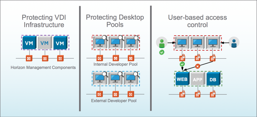
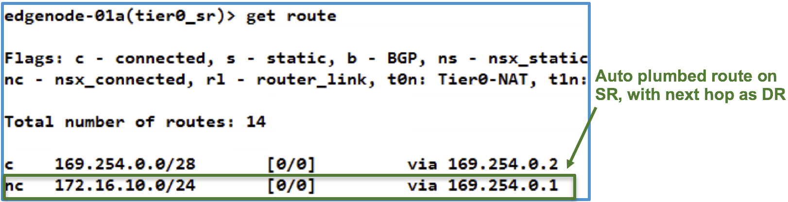
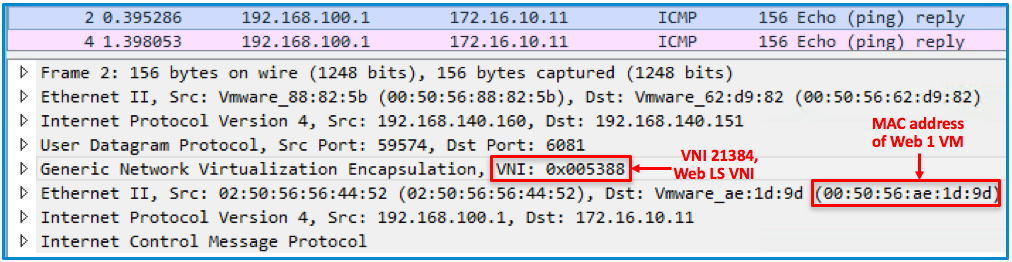
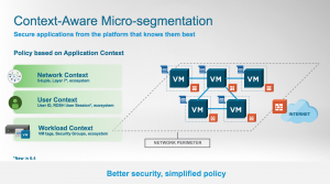
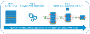
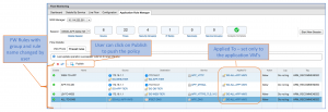
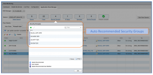
Figure:  ARM recommended Security groups for 3-tier application

Figure:  Published ARM recommended DFW rules

 In summary, NSX 6.4.0 ARM recommendation engine enhances the existing ARM capability by automating

  • The application grouping based on the function,
  • Firewall policy based on the analyzed flow for a given ARM session and
  • Layer 7 Application identity of the flow.

 The ARM allows multiple sessions (five) simultaneously, which can be leveraged to automate & speed up the multiple application onboardings with the NSX micro-segmentation.

 For more details on NSX ARM, please refer to following previously published blogs and videos:

The post Rapid Micro-segmentation using Application Rule Manager Recommendation Engine appeared first on Network Virtualization.

Top 5 From The Last 3 Months

$
0
0


In today’s day and age, content is king. It’s nearly impossible to keep up with the deluge of information, especially in the tech space where change is constant. We’re aware that the struggle is real. To keep you up-to-date on the latest and greatest in networking, we’ve compiled a round-up blog of the top posts from the past few months.


VMware Closes Acquisition of VeloCloud Networks

 In December, VMware NSX completed its acquisition of VeloCloud Networks, bringing their industry-leading, cloud-delivered SD-WAN solution to our own growing software-based networking portfolio. The acquisition of VeloCloud significantly advances our strategy of enabling customers to run, manage, connect and secure any application on any cloud to any device. Learn all about the acquisition from SVP and GM, Networking and Security Business Unit Jeff Jennings.

VMware SDDC with NSX Expands to AWS

With VMware Cloud on AWS, customers can now leverage the best of both worlds – the leading compute, storage and network virtualization stack enabling enterprises for SDDC can now all be enabled with a click of a button on dedicated, elastic, bare-metal and highly available AWS infrastructure. Bonus: because it’s a managed service by VMware, customers can focus on the apps and let VMware handle the management/maintenance of the infrastructure and SDDC components.

Introducing NSX-T 2.1 with Pivotal Integration

 In early December, NSX-T 2.1 was released, which enables advanced networking and security across emerging app architectures. More specifically, NSX-T 2.1 serves as the networking and security platform for the recently announced VMware Pivotal Container Service (PKS), a Kubernetes solution jointly developed by VMware and Pivotal in collaboration with Google. NSX-T 2.1 also introduces integration with the latest 2.0 release of Pivotal Cloud Foundry (PCF), serving as the networking and security engine behind PCF. Get a full download of all the functionality in NSX-T 2.1 by clicking the link above.

VMware Cloud on AWS with NSX: Connecting SDDCs Across Different Regions

One of the major benefits of VMware Cloud (VMC) on AWS is that users can easily achieve a global footprint by deploying multiple VMC SDDCs in different regions. At the end of 2017, two AWS regions became available for VMC: US West (Oregon) and US East (N. Virginia). By clicking a button and deploying SDDCs in different regions, users will have access to a global SDDC infrastructure backed by all the vSphere, vSAN and NSX functionality they love. Be on the lookout for more available regions coming this year.

Kubernetes in the Enterprise with VMware NSX-T and vRealize Automation

Part one of this five-part series centered around Kubernetes in the enterprise is a VMware guide on how to design, deploy and operate Kubernetes SaaS with NSX-T and vRealize Automation. This is a great entry piece to Kubernetes as a technical solution for the enterprise, with an emphasis on NSX-T’s networking and security integrations with the software.

There you have it! You’re now up-to-date in the Network Virtualization world.


Stay tuned to the VMware NSX blog for all the latest around network virtualization, and be sure to ‘Like’ us on Facebook and follow us on Twitter.

The post Top 5 From The Last 3 Months appeared first on Network Virtualization.

Context-Aware Micro-segmentation – an innovative approach to Application and User Identity Firewall

$
0
0

Summary: With Context-awareness, NSX for vSphere 6.4 enables customers to enforce policy based on Application and Protocol Identification and expands the Identity Firewall support to Multiple User Sessions.

A few weeks ago, VMware released version 6.4 of NSX for vSphere.  The 6.4 release brings many new features, with Context-awareness being key from a security perspective.  Micro-segmentation enables East-West security controls, and is a key building block to a secure datacenter. Context-awareness builds-on and expands Micro-segmentation by  enabling customers even more fine-grained visibility and control.  NSX has supported the use infrastructure or application-centric constructs such as Security Groups based on criteria like VM name or OS version, or Dynamic Security Tags describing things like the workload function, the environment it’s deployed in, or any compliance requirements the workload falls under, enabling fine-grained control and allowing customers to automate the lifecycle of a security policy from the time an application is provisioned to the time it’s decommissioned. Prior to 6.4, rules with  infrastructure or application-centric grouping constructs on the Management plane, are eventually translated to 5-tuple based rules in the dataplane.

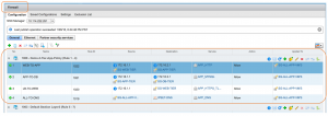
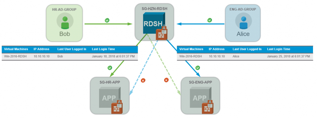
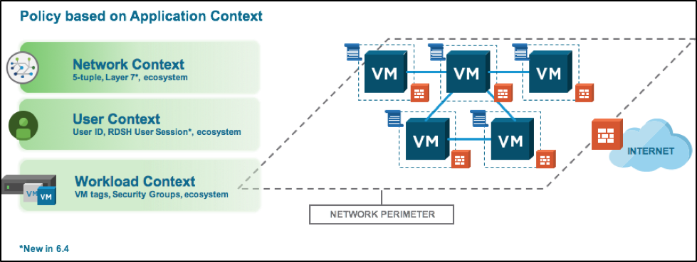
Figure: NSX drives policy based on Network, User and Workload Context

A crucial aspect of Context-awareness is that we support the use objects different than the traditional 5-tuple directly in the dataplane without having to the management plane “translating” these objects to IP addresses, protocols and ports.

Context-Aware Architecture

Under the hood, the key architectural components enabling context-awareness are the Context-Engine and Context-table along with other components that allow us to discover contextual information for every connection. The Context-Engine is a user-space component that resides on every host in an NSX-prepared cluster. It receives discovered contextual information and programs the Context-Table with that information.  The Context-Table keeps track of Context-Attributes for every flow going through the distributed firewall filter. Every new connection along with it’s Context-Attributes is then checked against the Distributed Firewall Rule-set and is mapped to a rule, not just based on 5-tuple but also based on the context-attributes specified in the rule.

In the 6.4 release, two new features take advantage of this context-aware architecture, Application and Protocol Identification and Multi-session Identity Firewall.


Figure: NSX 6.4 Context-Aware Architecture

Application and Protocol Identification

Application and Protocol Identification is the ability identify which application a particular packet or flow is generated by, independent of the port that is being used.  In addition to visibility into flows, enforcement based on application identity is another key aspect, enabling customers to allow or deny applications to run on any port, or to force applications to run on their standard port. Deep Packet Inspection (DPI) is foundational to this functionality, it enables matching of packet payload against defined patterns, commonly referred to as signatures.


Figure: NSX Native Distributed Firewall now acts on Layer 7 as well as L2 – L4

Getting Layer 7 visibility into East-to-West application flows in a datacenter and being able to enforce policy based not only on port but also based on the Layer 7 application identification, enables customers to reduce the attack surface even further.  The Application and Protocol Identity feature in NSX for vSphere 6.4 enables visibility across a large number of applications and enforcement based on applications commonly seen in enterprise datacenter infrastructure or application tiers such as Active Directory, DNS, HTTPS or MySQL.

Customers can use built-in Layer 7 Service Objects for port-independent enforcement or  create new Service Objects that leverage a combination of Layer 7 Application Identity, Protocol and Port. Layer 7 based Service Objects can be used in the Firewall Rule table and Service Composer, and application identification information is captured in Distributed Firewall logs, Flow Monitoring and Application Rule Manager (ARM) when profiling an application.

Key use-cases for Application and Protocol Identification are centered around Layer 7 visibility and enforcement across Infrastructure services, Intra/Inter Application and VDI/End User Compute:


  • Enforcement based on both Port and Layer 7 App-ID enabling customers to further reduce the attack surface by ensuring only the intended application can run across a given port

  • Blocking of Vulnerable Application Versions allowing customers to enforce the use of more secure/less vulnerable versions
  • Blocking of Vulnerable Application Versions allowing customers to enforce the use of more secure/less vulnerable versions

  • Application Layer 7 Visibility enables customers to discover what applications and application versions (TLS) are being used

Application and Protocol Identification in Application Rule Manager

Application Rule Manager (ARM) was introduced in NSX for vSphere 6.3,  and enables customers to automate application profiling and rapidly apply the appropriate whitelisting policy. In NSX for vSphere 6.4, ARM has been augmented with the Recommendation Engine, which is covered in detail in this blog post by my colleague Ganapathi. In addition to the recommendation engine, ARM now also has visibility into layer 7 context.

During the “Flow Monitoring” phase, ARM will learn about flows coming in/out of the application being profiled as well as flows in between application tiers. It will also learn about any Layer 7 Application Identity for the flows being discovered. This layer 7 visibility in ARM provide additional validation for Security teams that a particular flow should or should not be allowed in a zero-trust policy model. In addition to visibility, ARM also provides customers the ability to create new Layer 7 Service Objects outside of the list of ~50 built-in layer 7 services. For instance, if ARM discovers Bittorrent traffic, security teams can create an L7 service object for Bittorrent in order to explicitly allow/deny this application.


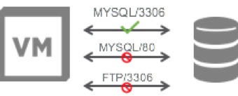
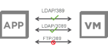
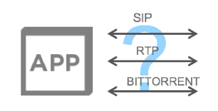
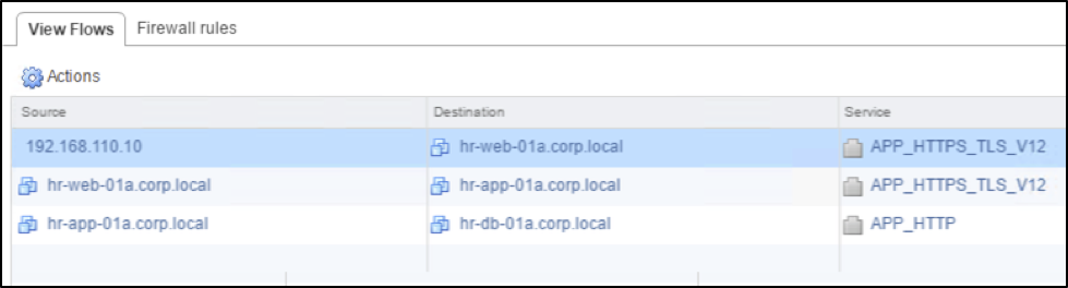
Figure: Intra-application flows identified based on Layer 7  Application Rule Manager

Application and Protocol Identification in Live Flow Monitoring

Live Flow Monitoring provides visualization of flows as they traverse a particular vNIC. This enables quick troubleshooting. As of NSX for vSphere 6.4, application context is also captured in Live Flow Monitoring for flow that match an L7 rule. Application fingerprinting in Live Flow Monitoring is available for over 1000 applications.

Figure: Live Flow Monitoring with Application Context

Application and Protocol Identification in Distributed Firewall Logs

With the Distributed Firewall, logs can be enabled/disabled on a per-rule basis. Any flow that is matching a rule with an L7 service object and logging enabled will trigger a log that contains the Application ID. Vrealize Log Insight can be used to gain additional insight into logs including the Distributed Firewall Logs

Architecture for Application and Protocol Identification

The context-aware architecture (described above) in NSX for vSphere 6.4 enables Application and Protocol Identification by keeping track of the Application-ID attribute for every flow in the Context-table. In addition to the Context-Engine and Context-Table, the Deep Packet Inspection (DPI)-Engine analyzes every flow and determines the L7 application Identity. After it has determined the App-ID, the Context Engine updates the Context Table flow entry with the appropriate application attribute. The flow is then re-evaluated against all rules that match the App-ID as well as 5-tuple, the flow table is updated and the appropriate enforcement action is taken.


Figure: Application Identification is kept in the Context Table

Configuring Application and Protocol Identification

Configuring a Distributed Firewall policy that leverages Application and Protocol Identification can be done using the Firewall Rule Table or using Service Composer. Regardless of which method you are using, here are the basic steps to follow:

  1. Create the appropriate Service Object
    • Go to Groups and TagsService
    • Select Layer 7 and specify App ID, Protocol and Port
    • Note: for port-independent enforcement, this step can be skipped.
  2. Use the Service Object in a rule/policy
    • Create a new DFW rule (first create a new policy when using Service Composer)
    • Choose the appropriate Source/Destination as usual
    • In the service field, select the L7 service object you have created earlier, or for port-independent enforcement, choose one of the ~50 built-in L7 service objects (name starting with APP_)
    • Choose the appropriate action (allow/deny)
    • Enable logging if required
    • Save the rule and publish the changes.

                      Figure: Adding a new Layer 7 Service Object                                          

Figure: Intra-Application Policy using Layer 7 Service Objects

Demo

Here’s a quick demo showing how NSX Application and Protocol Identification is configured and how it works.

Multi-session Identity Firewall

VMware introduced Identity Firewall feature with the NSX for vSphere 6.0 release. Identity Firewall allows customers to create firewall rules based on Active Directory user groups.  Prior the the NSX 6.4 release, Identity Firewall has been primarily used for Virtual Desktop Infrastructure (VDI) where it enables a different set of policies to be applied to a Virtual Desktop depending on the user who logs in to the desktop. With VDI, a Virtual Desktop is allocated to a single user. Upon user login, NSX determines the user-to-IP mapping either using NSX Guest Introspection Framework or Active Directory Log Scraping and adds those IP addresses into relevant Security Groups and Rules at the hypervisor dataplane where the rules are enforced.  This enables a highly scalable deployment in VDI environments.

Many of our customers also leverage Microsoft’s Remote Desktop Services (RDSH) or Virtual User Sessions besides VDI, especially for single application delivery. VMware Horizon or Citrix XenApp can both provide application deployment and access use RDSH services.

With NSX for vSphere 6.4, we are expanding the Identity Firewall use-case by enabling support for RDSH.  This means that with 6.4, multiple users can be logged in to the same Remote Desktop Session Host, and an appropriate Distributed Firewall ruleset will be applied to each user.  We have also extended User Identity to the Endpoint Monitoring feature.  Customers can now use Endpoint Monitoring along with Application Rule Manager to profile applications and map flows to applications, processes, and the user who is running the process.

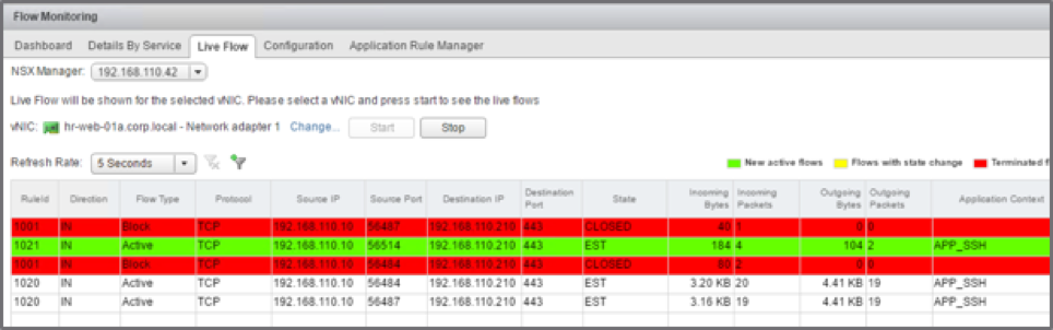
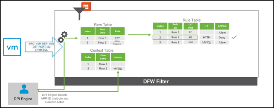
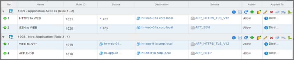
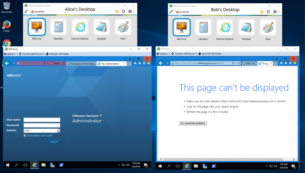
Figure: Virtual Desktop Infrastructure and Virtual User Sessions

Architecture for Multi-session Identity Firewall

Similarly to Application and Protocol Identification, the Multi-session Identity Firewall feature leverages the context-aware architecture in NSX for vSphere 6.4. First of all, the context-aware architecture allows the use of attributes different from 5-tuple in the dataplane.  With regards to Identity Firewall, this means that NSX Manager no longer need to translate users to IP address at the dataplane as was the case prior to 6.4. The Security Identifiers (SIDs) of a user can now be programmed directly at the dataplane and incoming flows can be matched against them.  A new option is available when creating a new Firewall Section or Policy in Service Composer which defines that directory-group based security groups within the section/policy should be programmed directly as SID-attributes in the dataplane ruleset. See details below on how to configure this.

Once the appropriate policy has been configured, flows from remote user sessions will be evaluated against the configured policy.  Using the VMware Tools Thin Agent along with Guest Introspection (GI) Framework, NSX is able to determine if a particular VM is an RDSH host. When a user logs in to an RDSH host and generates TCP flows, the Context-Engine leverages event information from the Guest Introspection Service Virtual Machine (GI SVM) to update the Context Table with a new entry mapping the user’s group Security Identifiers (SIDs) to the flow. The flow on the datapath along with the mapped SID is then matched against the Distributed Firewall rules that have Security Groups based on user-identity and the appropriate enforcement action is taken.


Figure: User-Context (SID) is maintained in the Context Table

Configuring Multi-session Identity Firewall

Prior to configuring Multi-session Identity Firewall, there are some prerequisites that need to be met.  

  • Active Directory must be integrated with NSX Manager
  • VMware Tools must be running on the RDSH VM
  • NSX for vSphere 6.4 along with  Guest Introspection SVM 6.4 needs to be deployed on all hosts

Once prerequisites have been met, you can configure Distributed Firewall rules to be applied to Multiple user session following the below steps, either using the Firewall Rule Table or Service Composer:

  1. Create a Security Group based on the applicable Active Directory Group (do not use any other membership criteria)
    • Go to Service ComposerSecurity Groups
    • Select the appropriate Directory Group(s) under Objects to Include
    • Note: do not include any other membership criteria besides Directory Groups
  2. Create a new Distributed Firewall Section or Service Composer Policy and check Enable User Identity at source
    • Note: No translation from users to IP happens for rules in this section/policy
    • Use the earlier created Security Group as source in the rule(s)

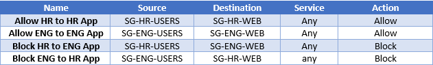
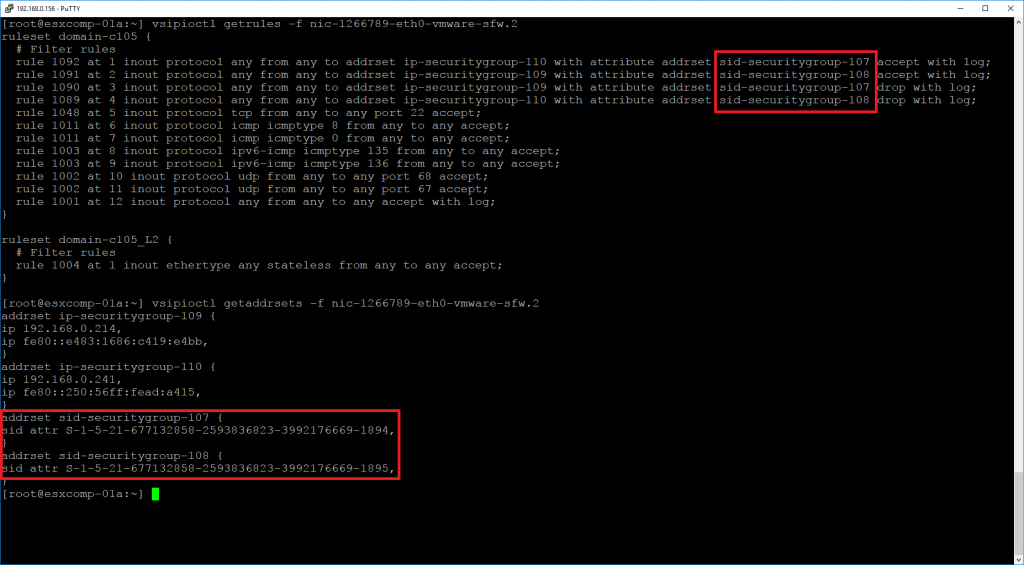
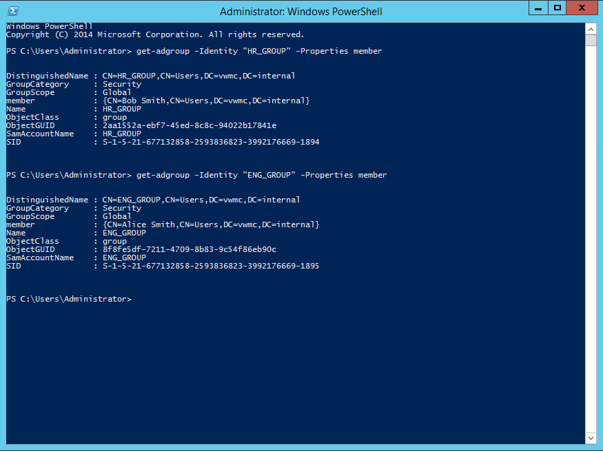
Figure:  Defining a Security Group based on Directory Group Membership   


Figure:  Rules based on User Identity

Demo

In this 5 minute demo, I’m reviewing some of the basics behind Multi-session Identity Firewall before showing how to user user-session based firewall rules.


The post Context-Aware Micro-segmentation – an innovative approach to Application and User Identity Firewall appeared first on Network Virtualization.


Context-Aware Micro-segmentation – Remote Desktop Session Host Enhancements for VMware Horizon

$
0
0

In a previous post my colleague, Stijn, discussed the enhancements to how NSX for vSphere 6.4 handles Remote Desktop Session Host, RDSH, systems with the Identity-based Firewall and Context-Aware Micro-segmentation.

Remote Desktop Services is an underlying technology from Microsoft that many vendors take advantage of to provide overlay management and application deployment technologies for.  In this post, we’re going to discuss how NSX for vSphere 6.4 allows customers to run RDS hosts with granular security for VMware Horizon systems.

VMware Horizon can provide multiple users the ability to connect to a single system to access their applications using the RDSH technology.  These users can be of the same type, for example all HR users, or of multiple types, HR and Engineering users.  In previous versions of NSX, it was not possible to individually secure user sessions and create Distributed Firewall (DFW) rule sets according to the user session logged into an RDSH server.  This meant less flexibility in controlling what users could access data center application servers without isolating one set of users to one RDSH server.  This model created a very rigid architecture for Horizon customers to follow.

Horizon allows customers to spin up Windows Server systems with the RDSH components installed on them and the Horizon agent, for users to connect into.  These systems can be brought up and down as needed.  Users can also connect through the Horizon Client and gain access to published Applications.  These applications are hosted on RDSH servers and security can be provided the same way regardless of entry point into the RDSH back-end.  In this post, we will show that logging into an RDSH desktop or through the Horizon published application, will allow us to granularly control security.

NSX for vSphere 6.4 provides a very granular security approach to providing Identity-based context to creating DFW rule sets for RDSH systems.  We’re going to look at the problem identified above, how to allow both HR and Engineering users access to the same RDSH system, but only allow each user to access specific data center application servers and block access to ones they shouldn’t have.

In our environment, we have Horizon installed with an RDSH system configured for access by our HR and System Engineering users, Bob and Alice.

Requirements

  • Bob requires access to the HR Application
  • Alice requires access to ENG Application
  • Bob should not have access to ENG Application
  • Alice should not have access to the HR Application

Environment

Horizon Configuration

In our environment we have one RDSH system for Horizon that serves not only published applications but can act as an RDSH session host and provide a full desktop to the end user if required.  This server will be the connection point to launch a browser to access the respective applications and to launch a full RDS desktop to access the application.

NSX Configuration

The first thing we need to do is configure Active Directory synchronization in the NSX Manager.  Look at this documentation on how to add an Active Directory domain to the NSX Manager.  We should see a Last Synchronization State of ‘SUCCESS’ and a corresponding timestamp that is valid.

We can configure and NSX Security Groups and add in the Directory Groups for HR and Engineering into their own Security Groups.  We will use these Security Groups to create our DFW rule sets.

NSX rules can now be built using the NSX Security Groups for each set of users.  RDSH session identity is established in the DFW by creating a new DFW Section and enabling the ‘Enable User Identity at source’ checkbox.  This will tell the DFW to look at the source as containing user Identities and will make the translation to their Active Directory Group SID for enforcement.

We need to write our rules for each of these AD Groups and users accordingly.

We put the Security Group for HR in the source of one rule, the server running the application that the HR users require access to run the application.  We do the same for the Engineering Security Group and add in the ENG Web Server as the destination application server for them to access.  Below this we will write a Block rule to the destination for each of the user groups, preventing them from accessing resources they shouldn’t be.


With the DFW rules in place, we can connect using the Horizon client as both users.  Once logged as each of these different users we can check their access to their respective systems as well as check their block to systems they should not be accessing.

From this screenshot, we can see that Bob has access to the HR application as he should, and that Alice cannot access the HR Application.  Let’s see if Bob and Alice can access the ENG Application.

We can see now that Alice, our engineer, is able to access the ENG Application (Horizon Administrator) and that when Bob attempts to access, he’s met with denial as should be expected.  This demonstrates that NSX can help micro-segment RDSH systems, even if they are published applications on the same machine with different logged in users.  Next, we’ll try this with an actual RDS Desktop.

Both Bob and Alice are logged in to their respective RDS session and we can see that they are indeed two different desktops, but are both being presented by the same RDS server.  Now we can perform the same tests we did when we logged into the published application.

We’ll try the reverse and attempt to access the other applications, and we see that we’re getting the same results.  Alice can now get to her application and Bob is denied access as expected.

Looks like our rules are working as they should.  In NSX for vSphere 6.4, we can click on the Security Group for each of the user groups and see the last logged on user in that group and from what server they’re logged into.  We can see that both Bob and Alice are accessing the same RDSH host with an IP address of 172.25.16.53.  Let’s check the DFW Security Groups and then the filter rules to show how the information the DFW is using for each rule set.

NSX is showing proper identities in the Security Group details for each user and their respective Active Directory Group.  But let’s look at these rules at the data plane level.

The main takeaway here is that for RDSH-enabled sections in the DFW, NSX uses the Active Directory Group SID instead of the IP address for mapping rule sets.  NSX translates these users into their respective Active Directory Security ID’s (SID) as part of the data plane rule set.  Let’s double check Active Directory to verify the group SIDs.

We can see that the SIDs ending in 1314 and 1315 represent the Active Directory group SIDs and hence we have our match.

NSX for vSphere 6.4 introduces some great new capabilities in being able to secure RDSH systems at a per-session and per-user level.  This granular security approach means less operational complexity overall for customers and more flexibility in which users can connect and run their applications on which host system.

The post Context-Aware Micro-segmentation – Remote Desktop Session Host Enhancements for VMware Horizon appeared first on Network Virtualization.

Introducing VMware NSX-T Reference Design

$
0
0
Available now is the VMware NSX-T Reference Design Guide, a deployment path to adopting NSX with diverse multi-domain workload requirements – multi-cloud (private/public), multi-hypervisor, and multiple application frameworks (VMs, PaaS and containers).


Since VMware acquired Nicira almost five years ago, NSX for vSphere has become de-facto standard for private cloud solutions, delivering key use cases in private cloud – namely security, automation and application continuity.  Since then, we’ve witnessed our customers datacenter and workload requirements changing; therefore, the demand for a platform that not only can deliver current private cloud requirements, but now many enterprises are looking for integration with the likes of cloud native apps, public/hybrid cloud, and other compute domains covering multiple hypervisors.

VMware NSX-T was introduced last year to meet the demands of the containerized workload, multi-hypervisor and multi-cloud. The NSX-T platform is focused on a diverse set of use cases – from private to public, traditional (multi-tiered architecture) to container (microservices architecture) based apps, automation and monitoring of security at IaaS, to programmatic devops workloads in PaaS and CaaS environments.  It is very important to start with an understanding of NSX-T architecture and its components, and some topics (ex. routing) have been discussed in other blog posts (routing pt1 and routing pt2), but today we are pleased to introduce a reference design guide that delivers the best practices and common design practices associated with NSX-T platform.  Below are some of the key attributes that make NSX-T architecture suitable for a variety of new workloads and domains:

  • vSphere agnostic yet multi-vCenter supported design
  • Multi-tenant routing with NAT & Load Balancer
  • Line rate forwarding (small to large packet sizes) via DPDK N-S Edge Node
  • Generalized container plug-in architecture
  • Multi-hypervisor micro-segmentation
  • Reduced complexity in routing configurations
  • Scale out distributed controller architecture

This is the first revision of the NSX-T Reference Design Guide and is aimed to deliver an architectural baseline.  Readers can expect technical details around deep packet walks for layer 2 & 3, security capabilities, and overall architecture design (ex. the design considerations for ESXi and KVM based environments).  The design chapter uses previously well adopted and understood design practices of NSX for vSphere architecture; however, NSX-T does not assume familiarity with NSX for vSphere and we treat knowledge of the platform independently.  Additionally, the design document covers the deployment guidelines of the bare metal edge node, as well as cluster design covering multi-VC ESXi deployment (including KVM only design).  As more customers deploy the NSX-T architecture and as new features get introduced to the platform, we will continue to update the document (for example, NSX-T 2.1 release supports platform load balancer) to provide design guidance.

In addition to the design guide, we are also sharing a container whitepaper covering the container related ecosystem from a technical standpoint, where we discuss a majority of the various offerings in this space – our goal is to provide guidance and education for any networking and security reader to get familiar with overall landscape, and then through that lens, understand the need for the development of NSX Container Plugin (NCP), which we will discuss briefly below.

There are two constants VMware is seeing with our customers in the enterprise that are looking at containers:

  1. Contrary to early perception – containers don’t replace VMs, rather containers are co-existing with BM and VM. This drives the need for consistent networking and security across all along with policy and visibility
  2. The commercial manifestation of container technology usually comes with some form of tools/provisioning/operational framework.  The goal is to uniquely interface with each (ex. Kubernetes, Pivotal Cloud Foundry) such that the provisioning of networking, security and automation becomes part of those tools directly, and not something that’s stitched together after the fact.  This alleviates the IaaS element provisioning into PaaS consistently and instead embeds as part of lifecycle of the PaaS infrastructure

Our goal with NSX is to provide native container networking.  More specifically, the ability to assign a unique IP address per container, the ability to provide routing services to the container, etc. which in the end, leads to a model where containers are promoted and treated the way administrators and operations handle VMs today.  Ultimately, this results in a single NSX network fabric that supports bare-metal, containers, and virtual machines communicating at layer 3.  This type of native container networking is absent from most of the CaaS and PaaS platforms that we mentioned earlier; therefore, in order to enable integration and abstraction across multiple platforms, we developed the NCP (NSX Container Plugin).

Lastly, for customers that are looking for more details beyond containers and want to learn more about some of our cloud offerings, you can now find detail on how NSX-T applies to cloud centric architectures by heading on over to NSXCLOUD services, which are part of other cloud services offered by VMware.


2018 is finally upon us and we’ve heard our customers loud and clear.  These requirements for multi-cloud, multi-hypervisor, and multi-app frameworks are simply becoming table stakes driving many of their latest IT projects.  If you’re like me and prefer learning more by taking the hands-on approach, you’re in luck!  The latest NSX-T Hands-on Labs are available here… and don’t forget to let us know why you choose to #RunNSX:

HOL-1826-01-NET – VMware NSX-T – Getting Started

HOL-1826-02-NET – VMware NSX-T with Kubernetes

The post Introducing VMware NSX-T Reference Design appeared first on Network Virtualization.

Context-Aware Micro-segmentation – Remote Desktop Session Host Enhancements for Citrix

$
0
0

In a previous post by my colleague, Stijn, discussed the new changes to how NSX for vSphere 6.4 handles Remote Desktop Session Host, RDSH, systems with the Identity-based Firewall and context-aware micro-segmentation.

RDSH is an underlying technology from Microsoft that many vendors take advantage of to provide overlay management and application deployment technologies for.  In this post, we’re going to discuss how NSX 6.4 and the new changes to support RDSH hosts works with Citrix XenApp systems.

Citrix XenApp can provide multiple users the ability to connect to a single system to access their applications using the RDSH technology.  These users can be of the same type, for example all HR users, or of multiple types, HR and Engineering users.  NSX has supported User Identity based firewalling for Virtual Desktops since the 6.0 release, but it did not address RDSH in which multiple user sessions are connecting to the same host  This meant less flexibility in controlling what users could access data center application servers without isolating one set of users to one RDSH server.  This model created a very rigid architecture for XenApp customers to follow, which brought about the use of Virtual IP addressing.

To combat the issue of each session having the same IP address in an RDS environment, Microsoft brought in Virtual IP technology back in Windows Server 2008 R2, which Citrix leveraged to provide a new IP address for each user session on an RDS host.

Virtual IP Technology

Pros

  • This helped provide more granular security by being able to institute security policies based on the session IP address
  • Useful for things like licensing of software where the IP and MAC address needs to be different

Cons

  • Requires DHCP infrastructure and more complexity added to the environment with creating loopback networking as well.
  • Requires changing registry entries on each of the RDS hosts.

Identify Firewalling for RDSH in NSX, does not require any changes to the guest OS system.  It does not require additional DHCP infrastructure and provides the same per-user session security that Virtual IP addressing can, with significantly less complexity and a similar operational experience to typical DFW rule set building.

Citrix provides the ability to access applications through the StoreFront web portal, or access RDS host systems to get a full published desktop for the user to consume.  This provides great flexibility in how a user can perform tasks.  In this post we will show that logging into a XenApp published application or an RDSH published desktop will allow us to granularly control security regardless of entry method.

NSX for vSphere 6.4 provides a more granular approach to creating Distributed Firewall policies for virtual user sessions by leveraging identity-based context.   We’re going to look at the problem identified above, how to allow both HR and Engineering users access to the same RDSH system, but only allow each user to access specific data center application servers and block access to ones they shouldn’t have.

In our environment, we have Citrix installed with an RDSH system configured for access by our HR and System Engineering users, Bob and Alice.

Requirements

  • Bob requires access to the HR Application
  • Alice requires access to ENG Application
  • Bob should not have access to ENG Application
  • Alice should not have access to the HR Application

Environment

Citrix Configuration

In our environment we have one RDSH host for Citrix that serves not only published applications but can also provide a full published desktop if the end user requires it.  This system will be accessed by browsing to the StoreFront web interface, logging in and selecting the appropriate connections means, in this case both a web browser published app, and the web browser in the full desktop.

NSX Configuration

The first thing we need to do is configure Active Directory synchronization in the NSX Manager.  Look at this documentation on how to add an Active Directory domain to the NSX Manager. We should see a Last Synchronization State of ‘SUCCESS’ and a corresponding timestamp that is valid.


We can configure NSX Security Groups and add in the Directory Groups for HR and Engineering into their own Security Groups.  We will use these Security Groups to create our DFW rule sets.


NSX rules can now be built using the NSX Security Groups for each set of users.  RDSH session identity is established in the DFW by creating a new DFW Section and enabling the ‘Enable User Identity at source’ checkbox.  This will tell the DFW to look at the source as containing user Identities and will make the translation to their Active Directory Group SID for enforcement.


We need to write our rules for each of these AD Groups and users accordingly.

We put the Security Group for HR in the source of one rule, the server running the application that the HR users require access to run the application.  We do the same for the Engineering Security Group and add in the ENG Web Server as the destination application server for them to access.  Below this we will write a Block rule to the destination for each of the user groups, preventing them from accessing resources they shouldn’t be.


With the DFW rules in place, we can connect to from our clients to the StoreFront web site, and launch our connections to the Citrix RDSH server as each of these different users and check their access to their respective systems as well as check their block to systems they should not be accessing.


From these screenshots, we can see that Bob has access to the HR application as he should, and that Alice cannot access the HR Application.  Let’s see if Bob and Alice can access the ENG Application.


We can see now that Alice, our engineer, is able to access the ENG Application (Horizon Administrator) and that when Bob attempts to access, he’s met with denial as should be expected.  This demonstrates that NSX can help micro-segment RDSH systems, even if they are published applications on the same machine with different logged in users.  Next, we’ll try this with an actual RDS Desktop.


Both Bob and Alice are logged in to their respective RDS session and we can see that they are indeed two different desktops, but are both being presented by the same RDS server.  Now we can perform the same tests we did when we logged into the published application.


We’ll try the reverse and attempt to access the other applications, and we see that we’re getting the same results.  Alice can now get to her application and Bob is denied access as expected.

Looks like our rules are working as they should.  In NSX for vSphere 6.4, we can click on the Security Group for each of the user groups and see the last logged on user in that group and from what server they’re logged into.  We can see that both Bob and Alice are accessing the same RDSH host with an IP address of 172.16.50.7.  Let’s check the filter rules to show how the information the DFW is using for each rule set.


NSX is showing proper identities in the Security Group details for each user and their respective Active Directory Group.  But let’s look at these rules at the data plane level.


The main takeaway here is that NSX is no longer translating user ID’s to IP addresses in RDSH-enabled DFW sections.   NSX is translating these users into their respective Active Directory Security ID’s (SID) as part of the data plane ruleset.  Let’s double check Active Directory.


We can see that the SIDs ending in 1894 and 1895 represent the Active Directory group SIDs and hence we have our match.

With Context-awareness, NSX for vSphere 6.4 introduces some great new capabilities, including the ability to provide per-user and per-user-session policy enforcement regardless of the underling RDSH host users are connecting to.   This granular security approach means less operational complexity overall for customers and more flexibility in which users can connect and run their applications on which host system.

The post Context-Aware Micro-segmentation – Remote Desktop Session Host Enhancements for Citrix appeared first on Network Virtualization.

NSX-T: Multi-Tiered Routing Architecture

$
0
0

Multi-tenancy exists in some shape or form in almost every network, but we’ve come to learn that not every operator or administrator has a unified definition of what that means exactly. For an Enterprise network, it can often be viewed as the separation of tenants based on different business units, departments, different security/network policies or compliance requirements. Conversely, for a service provider, multi-tenancy can simply be separation of different customers (tenants).

Multi-tenancy doesn’t just allow for separation of tenants, but it also provides control boundaries in terms of who controls what. For instance, tenant administrators can control/configure the network and security policies for their specific tenants and a service provider administrator can either provide a shared service or provide inter-tenant or WAN connectivity.

In the logical routing world of NSX-T, this provider function can provide connectivity between the tenant logical networks and  physical infrastructure. It can also provide inter-tenant communication or some shared services (like NAT, Load Balancer etc.) to the tenants.

In my previous post, NSX-T: Routing where you need it (Part 1), I discussed how NSX-T provides optimized E-W distributed routing and N-S centralized routing. In addition to that, NSX-T supports a multi-tiered routing model with logical separation between provider router functions and tenant routing functions. The concept of multi-tenancy is built directly into the platform and is reflected in the routing model. The top-tier logical router is referred to as Tier-0 while the bottom-tier logical router is Tier-1. The following diagram shows the multi-tiered routing architecture.
Figure 1: Multi-Tiered Routing Architecture

Before we understand nuts and bolts of this architecture, let’s first address some common questions that our customers ask when evaluating NSX-T:

Is it mandatory to run multi-tiered routing?

The simple answer is no. You can have a single Tier-0 Logical router (LR) which can be connected to physical infrastructure northbound and connected to logical switches southbound. This single tiered approach provides you all the goodness of distributed E-W routing in kernel and centralized N-S routing, as discussed in my previous post.

Why would you want to run a multi-tiered routing topology?

This answer depends on the answer to following questions.

Do you want multiple tenants that need isolation?
Do you want to give provider admin and tenant admin complete control over their services and policies?
Do you want to leverage a CMP (Cloud Management Platform) like openstack to deploy these tenants?
Are you leveraging NSX-T to provide networking/security for Kubernetes/PCF(Pivotal Cloud Foundry)?

If the answer to any one of the above questions is yes, then, you need a multi-tiered routing topology.  Let me explain some of the benefits of multi-tiered routing architecture.

  • This architecture gives both provider administrator and tenant administrators complete control over their services and policies. Provider administrator controls and configures Tier-0 routing and services, and tenant administrators control and configure their tenant specific Tier-1 logical routers.
  • This architecture also eliminates the dependency on physical infrastructure administrator to configure or change anything when a new tenant is configured in the Datacenter.
  • Easy CMP integration. Using openstack, you just have to deploy Tier-1 logical routers and connect them to the pre-configured Tier-0 logical router. Tier-0 LR simply advertises the new tenant routes (learnt from tenant Tier-1 LR) on already established routing adjacency with the physical infrastructure.

How are the two tiers connected?

Tier-0 LR connects to one or more physical routers northbound using Uplink Port and connects to Tier-1 LRs or directly to logical switches southbound via a downlink port. Refer Figure 2 below.

Whereas, Tier-1 LR connects to a Tier-0 LR (this link is known as RouterLink) northbound and it connects to one or more logical switches southbound using Downlink port. Each tier-0-to-tier-1 peer connection is provided a /31 subnet within the 100.64.0.0/10 reserved address space (RFC6598). A user has the flexibility to change this subnet range and use another subnet if desired. This link is created automatically when you create a tier-1 router and connect it to a tier-0 router.

How routing works in multi-tiered architecture?

When a Tier-1 LR is connected to Tier-0 LR, management plane configures a default route on Tier-1 LR with next hop IP address as Routerlink IP of Tier-0 LR (100.64.128.0/31, in the following topology).

To provide reachability to subnets connected to the Tier-1 LR, the Management Plane (MP) configures static routes on the Tier-0 LR for all the LIFs connected to Tier-1 LR with a next hop IP address as Tier-1 LR Routerlink IP (100.64.128.1, in the following topology). 172.16.10.0/24 and 172.16.20.0/24 are seen as NSX Static routes on Tier-0 LR. Figure 2: Route advertisement on Tier-1 and Tier-0 LR

Fundamentals of DR(Distributed Router)/SR(Service Router) discussed in the previous posts remain the same for multi-tiered routing. When a user creates a Tier-1 or a Tier-0 LR, a DR instance is instantiated on all transport nodes (compute hypervisors and edge nodes).

If a centralized service is configured on either Tier-0 or Tier-1 LR, a corresponding SR is instantiated on the Edge node. For instance, when a Tier-0 is connected to physical infrastructure (centralized service), a Tier-0 SR is instantiated on the edge node. Similarly, when a centralized service like NAT is configured on Tier-1, a Tier-1 SR is instantiated on the Edge node.

Moving on, let’s take a look at the inter-tenant communication via Tier-0 LR. It’s important to note that NSX-T provides a fully distributed routing architecture which implies that all the logical routers (Tier-1 or Tier-0) will be distributed and run as kernel modules across all transport nodes.

Inter-Tenant East-West traffic

The following diagram shows a logical view and per transport node view of two Tier-1 LRs serving two different tenants and a Tier-0 LR, configured via NSX-T Manager. Per Transport node view shows that the Tier-1 DRs for both tenants and Tier-0 DR have been instantiated on two hypervisors. In the following topology, I have Web 1 VM (172.16.10.11) hosted on hypervisor HV1 in Tenant 1. I also have App1 (172.16.200.11) hosted on hypervisor HV1 and Web 2 VM (172.16.100.11) hosted on hypervisor HV2, both of these VMs belong to Tenant 2.
I have not configured any centralized services like NAT etc. on either of Tier-1 LR, so both tenant Tier-1 LRs just has the distributed component of LR, i.e. DR.
Figure 3: Multi-Tier distributed E-W Routing with workloads on same hypervisor


Multi Tiered Distributed Routing when workloads are on the same hypervisor

Following is the detailed packet walk between workloads in different tenants, but hosted on the same hypervisor (refer Transport Node View in Figure 3).

  1. Web1 VM 172.16.10.11 in Tenant 1 sends a packet to App 1 VM 172.16.200.11 in Tenant 2. The packet is sent to its default gateway interface located on the local HV1 Tier-1 DR (Tenant 1).
  2. Routing lookup happens on the Tenant 1 Tier-1 DR and the packet is routed to Tier-0 DR following the default route to Tier-0 DR Routerlink interface (100.64.128.0/31).

Figure 4: Tenant 1 Tier-1 DR forwarding table

       3. Routing lookup happens on Tier-0 DR which determines that 172.16.200.0/24 subnet is learnt via 100.64.128.3/31 i.e. Tenant 2 Tier-1 DR and packet is routed to Tenant 2 Tier-1 DR.

Figure 5: Tier-0 DR forwarding table 

       4. Routing lookup happens on the Tenant 2 Tier-1 DR which determines that 172.16.200.0/24 subnet is directly connected subnet. L2 lookup is performed in the local MAC table to determine how to reach App 1 VM and packet is sent to App 1 VM.

The reverse traffic from App 1 VM in Tenant 2 follows the similar process. Packet from App 1 VM to destination Web 1 VM, 172.16.10.11 is sent to Tenant-2 Tier-1 DR which follows the default route to Tier-0 DR. Tier-0 routes this packet to Tenant 1 Tier-1 DR and packet is delivered to Web 1 VM.

Multi-Tiered Distributed Routing when workloads are on the different hypervisor

The routing lookups pretty much remain the same as above with an additional step of traffic going on overlay between two hypervisors as the two VMs are hosted on different hypervisors.

Important point to note here is that the traffic from Web1 in Tenant 1 is  routed on HV1 and sent to HV2. The return traffic, however, is routed on HV2. Again, this goes back to the same concept that routing happens closest to the source.

Notice that the packet never left the hypervisor to get routed between Tenants. Let’s take a look at how this traffic flow would look like if these VMs in different tenants are also on different hypervisors.

Figure 6: Multi-Tiered distributed E-W Routing with workloads on different hypervisor

Let’s do traceflow to validate this. Notice that packet from Web 1 VM gets routed on HV1 (ESX-TN1) Tenant 1 DR, goes to Tier-0 which routes the packet to Tenant 2 Tier-1 DR and then the packet is encapsulated in GENEVE to be sent to HV2 (ESX-TN2).

Figure 7: Traceflow between VMs in different tenants

North-South Routing in Multi-Tiered Routing Architecture

Moving on, let’s take a look at N-S connectivity and packet walk from a VM connected to a Tenant Tier-1 router to a device in physical infrastructure. Now, since this packet is destined for a device in physical infrastructure, this packet will need to go through the Edge node.
I talked about centralized routing and how SR hosted on Edge node would handle N-S routing in a previous post, NSX-T: Routing where you need it (Part 2, North-South Routing). Leveraging the same concepts, I will show how N-S routing works for a multi-tier architecture.Figure 8: N-S Packet walk -Multi-Tiered Topology

  1. Web1 VM (172.16.10.11) in Tenant 1 sends a packet to 192.168.100.10. The packet is sent to the Web1 VM default gateway interface located on the Tenant 1 Tier-1 DR i.e.172.16.10.1.
  2. Routing lookup is done on Tenant 1 Tier-1 DR which has a default route to Tier-0. Refer output in figure 4.
  3. Tier-0 DR gets the packet and does the routing lookup and since there is no specific route for 192.168.100.0/24, packet will be routed using default route which points to 169.254.0.2. This is Intra-Tier transit link between the DR and SR. VNI 21389 has been auto assigned to the link between Tier-0 DR and its corresponding Tier-0 SR.

Figure 9: Tier-0 DR forwarding table

      4. MAC lookup is done for 169.254.0.2 and this MAC address is learnt via remote TEP 192.168.140.160 i.e. Edge Node.

Figure 10: ARP and MAC lookup

      5. ESXi host encapsulates the packet and sends it to Edge node.
      6. Edge Node TEP decapsulates the packet and removes the outer header upon receiving the packet.
      7. This packet is sent to Tier-0 SR (as the destination MAC address in the inner header is of Tier-0 SR).
      8. Tier-0 SR does routing lookup and sends the packet to the physical router following the BGP route, which routes it to 192.168.100.10.

Let’s take a look at the packet flow in reverse direction now.Figure 11: N-S Packet walk -Multi-Tiered Topology (Return Packet)

  1. External device 192.168.100.10 sends the return packet to Web1 VM (172.16.10.11) following the BGP route that was learnt via SR on Edge node.
  2. Routing lookup happens on Tier-0 SR which determines that 172.16.10.0/24 is learnt via Tier-0 DR.

Figure 12: Tier-0 SR Routing table

      3. Traffic is sent to Tier-0 DR via Intra Tier transit link between SR and DR.
      4. Tier-0 DR learnt this route via Tenant 1, Tier-1 DR and so, the packet is routed to Tenant 1, Tier-1 DR.

Figure 13: Tier-0 DR forwarding table

      5. Tier-1 DR does a routing lookup which determines that 172.16.10.0/24 is a directly connected subnet and it’s on LIF1 i.e the interface connected to Web-LS. A lookup is performed in LIF1 ARP table to determine the MAC address associated with Web1 VM IP address. This destination MAC is learnt via remote TEP 192.168.140.151 i.e. ESXi host where Web1 VM is hosted.
      6. Edge node encapsulates the packet and sends it to ESXi host.
      7. ESXi host decapsulates the packet and removes the outer header upon receiving the packet. A L2 lookup is performed in the local MAC table associated to LIF1.
      8. Packet is delivered to Web1 VM.

This concludes Multi-Tiered Routing architecture.

Learn More

https://docs.vmware.com/en/VMware-NSX-T/index.html

The post NSX-T: Multi-Tiered Routing Architecture appeared first on Network Virtualization.

Ready for Take-Off with Kubernetes, Cloud Foundry, and vSphere

$
0
0

A complex and diverse world

Singapore. Etihad. Wow. I always found it impressive when airlines were able to build a business and a brand without a significant domestic customer base to start off from. They instead focus on the global market, which is much more challenging. There is a competitive landscape of many players. There is the complexity of interconnecting a world of disparate lands and diverse customer cultures and preferences. An impressive feat.

The world of networking is becoming quite similar. From private, hybrid, and public cloud models, to increased use of SaaS, to the way SaaS and other apps are built using microservices architectures and containers, the landscape of islands to connect in an inherently secure and automated fashion is increasingly diverse and complex.

An app built to demonstrate this diversity

If the airline to networking analogy is lost on you, or you think it’s too much of a stretch, let me pull up the second reason I used planes in my symbolism. My brilliant colleague Yves Fauser built an app to demonstrate how NSX is connecting and securing this variety of new app frameworks, and it happens to be a “plane spotter” app. You may have already seen it demonstrated at Network Field Day 17 #NFD17 this past January. He pulls airplane data provided publically by the FAA, and ultimately connects it with flight status provided by a live feed from ADS-B. So for example, we were able to see if John Travolta’s airplane was in flight or not. It wasn’t. But still, pretty neat.

More importantly, from the networking and security perspective, this app was intentionally designed to have each app component running in a different platform, including:

  • Pivotal Container Service (PKS): Both the Redis database and the API service were deployed in Kubernetes clusters using PKS – which by the way went GA with version 1.0 just last week! In this case, NSX-T is not only tightly integrated but is a component of PKS, delivering container networking and security automatically as apps are spun up.
  • vSphere: The SQL database was deployed manually on a vSphere VM.
  • Pivotal Cloud Foundry: The web front end is running on Pivotal Application Service (PAS).
  • OpenShift: A program accepting the ADS-B feed and feeding it into the Redis database is running in an OpenShift container.


A cohesive networking and security strategy with VMware NSX

Across all of these platforms, NSX-T was automatically deploying network services, providing container level network visibility, and applying the associated security policies, as soon as “the developer” spun up that app component (e.g. “kubectl create -f” in K8s or “cf push” in cloud foundry). I don’t know if any environment plans to use all of these platforms in parallel like this, but the point here was to demonstrate what’s possible, achieving consistent networking and security services, functions, and tooling across a diverse landscape of environments.


What does it look like in detail, from both the perspective of the app developer and the network operator? Check out the demo!

The post Ready for Take-Off with Kubernetes, Cloud Foundry, and vSphere appeared first on Network Virtualization.

Viewing all 481 articles
Browse latest View live


<script src="https://jsc.adskeeper.com/r/s/rssing.com.1596347.js" async> </script>