I’ve written several prior blogs on multi-site solutions with NSX-V discussing topics such as fundamentals, design options, multi-site security, and disaster recovery; see below links to review some of the prior material. In this post, I’ll discuss how VMware NSX-V and F5 BIG-IP DNS (prior known as F5 GTM) can be used together for Active/Active solutions where an application is spanning multiple sites and site-local ingress/egress for the application is desired. F5 offers both virtual and physical appliances; in this post I demonstrate using only the virtual (VE) F5 appliances. Big thanks to my friend Kent Munson at F5 Networks for helping with the F5 deployment in my lab and for providing some of the details to help with this blog post. This is the first of several blog posts to come on this topic.
Prior NSX-V Multi-site and Disaster Recovery Posts:
With Cross-VC NSX, as shown in my prior blog post, Cross-VC NSX: Multi-site Deployments with Ease and Flexibility, there are multiple deployment options. A popular deployment model is shown bellow in Figure 1 where a single Universal Control VM peers with ESGs at both sites. BGP weight is used to control the egress point. BGP weight is used to enforce that all North/South traffic across both sites be sent out site 1 ESGs. In this example, the VMs on the Web tier (same subnet) are spanning both sites, but the BGP weight dictates via routing that all traffic egress site 1 ESGs. There are multiple options to control ingress traffic in this model, for example via route filtering on the site 2 ESGs or AS Path prepend on the ToRs. I’ve prior outlined these options in detail in the NSX-V Multi-site Options and Cross-VC NSX Design Guide.
![Figure 1: Cross-VC NSX Deployment with Active/Passive Ingress/Egress]() Figure 1: Cross-VC NSX Deployment with Active/Passive Ingress/Egress
Figure 1: Cross-VC NSX Deployment with Active/Passive Ingress/Egress
In this deployment model, a single egress point at site 1 is used for North/South traffic for both sites; this simplifies deployment, maintenance, and troubleshooting, and, typically, customers investing in such a multi-site solution have a robust data center interconnect (DCI) for the typical 15 – 20% or less North/South traffic seen within a data center.
If the requirement is simply to utilize ESGs at both sites for different applications, a deployment such as the below can also be done. In this example, Tenant 1 applications, primarily at site 1, use the site 1 ESGs for North/South traffic and Tenant 2 applications, primarily at site 2, use the site 2 ESGs for North/South traffic. This is accomplished by simply deploying another Universal Distributed Router (UDLR) for Tenant 2 and using BGP weight to prefer the routes out site 2 ESGs.
![Figure 2: Cross-VC NSX- Two UDLRs and Active/Passive Ingress/Egress Using ESGs at Both Sites]() Figure 2: Cross-VC NSX- Two UDLRs and Active/Passive Ingress/Egress Using ESGs at Both Sites
Figure 2: Cross-VC NSX- Two UDLRs and Active/Passive Ingress/Egress Using ESGs at Both Sites
Sometimes it’s desired to have Active/Active North/South connectivity for an application that is stretching across sites. For example, Web servers at site 1 should use the site 1 ESGs and Web servers at site 2 on the same subnet should use site 2 ESGs.
The application in this case is stretched across sites and we want to use the site-local ESGs for ingress/egress. There are a couple options here such as the Local Egress NSX feature and possible /32 host routes advertised by the ESGs. However, although possible, /32 host route injection would require additional automation to be done to account for when a VM vMotions across sites. In this post, we’ll discuss a solution leveraging F5 BIG-IP DNS alone which provides Global Server Load Balancer (GSLB) functionality. It is also possible to leverage the Local Egress NSX feature in combination with F5 BIG-IP DNS for specific use cases. This would require a slightly different design and will be discussed in a later blog post.
By using a GSLB solution such as F5 BIG-IP DNS with Cross-VC NSX, a complete solution for Active-Active with local site ingress/egress can be achieved for the desired applications as shown below. It should be noted, there are multiple NSX with F5 BIG-IP DNS deployment models that can be leveraged. In the below model, traffic that is initiated from the client and needs to be load balanced will leverage the local F5 LTMs for ingress and the return egress while other traffic that doesn’t have this requirement will use the respective ESGs based on the routing metric.
![Figure 3: Cross-VC NSX and F5 BIG-IP DNS Multi-site Deployment]() Figure 3: Cross-VC NSX and F5 BIG-IP DNS Multi-site Deployment
Figure 3: Cross-VC NSX and F5 BIG-IP DNS Multi-site Deployment
In this deployment two F5 LTM load balancers are deployed at each site in active/standby mode. There are four interfaces on the LTM VE appliance. In this example, the interfaces are used as such:
- Management interface: used for management of the LTM appliance and can be reached via web interface.
- HA interface: a heartbeat between the LTMs is used for monitoring and configuration synchronization purposes; in this case a NSX logical switch is used for this connectivity
- Internal interface: interface connected to the application network where servers that will be load balanced are connected; in this case the allocation network is also a NSX logical switch
- External interface: interface connected to the physical network
Source network address translation (SNAT) is done by the F5 LTM appliance and both an internal floating IP and external floating IP is configured as shown in Figure 3. As a client attempts to connect to a web server and makes a DNS request, the F5 BIG-IP DNS replies with the respective sites F5 LTM External Vitual IP (VIP) address. Which sites VIP is returned depends on the load balancing algorithm used. An example of this will be shown later in the post. Note, because this is a lab environment, private IP addresses were used.
In the below screenshot of the site 1 F5 BIG-IP DNS, it can be seen there is an entry in the F5 GSLB Wide IP List that responds to A queries for demoweb.nsxlab18.local.
![Figure 4: F5 BIG-IP DNS GSLB Wide IP List]() Figure 4: F5 BIG-IP DNS GSLB Wide IP List
Figure 4: F5 BIG-IP DNS GSLB Wide IP List
Looking at the associated pool (clicked 1 under Pools in Figure 4), we see that it has four members as shown below in Figure 5.
![Figure 5: F5 BIG-IP DNS GSLB Pool]() Figure 5: F5 BIG-IP DNS GSLB Pool
Figure 5: F5 BIG-IP DNS GSLB Pool
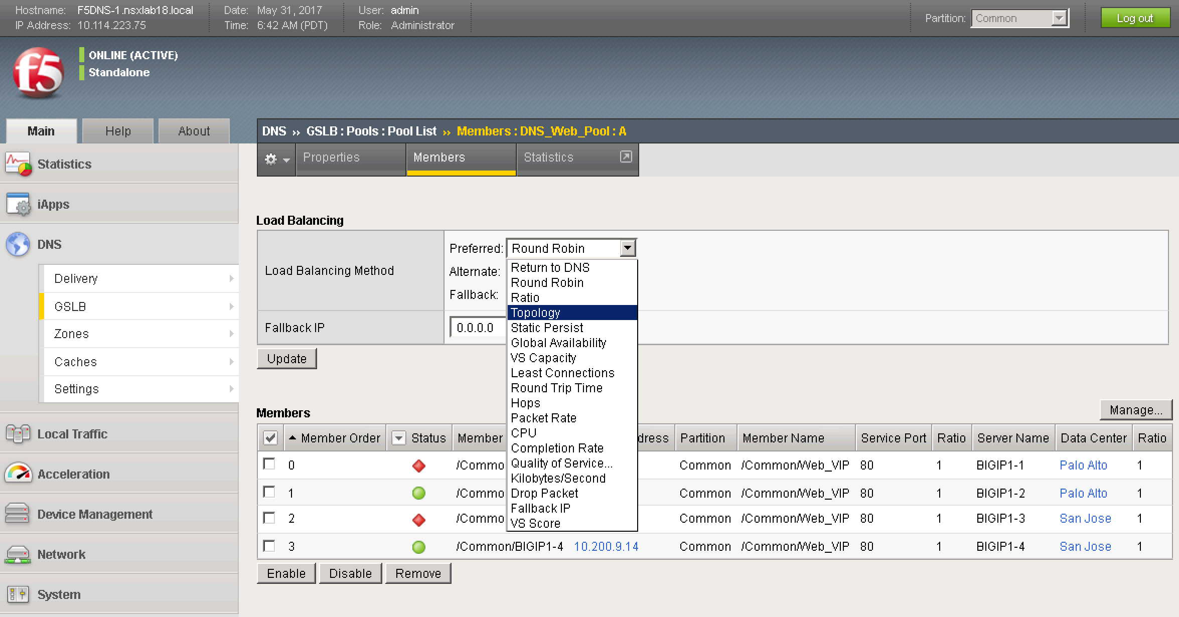
Clicking on the number 4 under members, we can see the site-specific LTMs and their associated VIPs. The active LTMs have a status of green and the standby LTMs have a status of red.
![Figure 6: F5 BIG-IP DNS GSLB Pool Members]() Figure 6: F5 BIG-IP DNS GSLB Pool Members
Figure 6: F5 BIG-IP DNS GSLB Pool Members
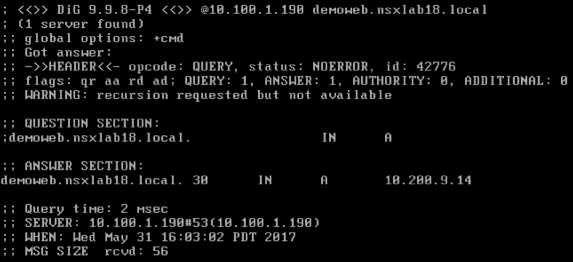
Also, note, in Figure 6, the Load Balancing Method is currently set to Round Robin. Since, in our current setup we have the Web application spanning both sites with one Web VM at each site, as clients make requests, they will be sent to the Web servers across sites in round-robin fashion. This is shown in the screen shots further below. The first query to the site 1 DNS server returns the External VIP for site 1: 10.100.9.14, a second query returns the External VIP for site 2: 10.200.9.14, a third query round-robins back to the External VIP for site 1: 10.100.9.14. The same behavior is seen when hitting the site 2 DNS.
![Figure 7: Site 1 DNS Reply to First Query]() Figure 7: Site 1 DNS Reply to First Query
Figure 7: Site 1 DNS Reply to First Query
![Figure 8: Site 1 DNS Reply to Second Query]() Figure 8: Site 1 DNS Reply to Second Query
Figure 8: Site 1 DNS Reply to Second Query
![Figure 9: Site 1 DNS Reply to Third Query]() Figure 9: Site 1 DNS Reply to Third Query
Figure 9: Site 1 DNS Reply to Third Query
F5 BIG-IP DNS supports numerous load balancing algorithms and can also distribute DNS name resolution requests using proximity-based load balancing. F5 BIG-IP DNS determines the proximity of the resource by comparing location information derived from the DNS message to the topology records in a topology statement that has been preconfigured. The Topology Load Balancing Method should be used if it is desired to send requests from a client in a particular geographic region to a data center or server located in that region; this effectively helps achieve site-local routing for active-active solutions. Figure 10 below shows the numerous load balancing methods that are available.
![Figure 10: F5 BIG-IP DNS GSLB Load Balancing Options]() Figure 10: F5 BIG-IP DNS GSLB Load Balancing Options
Figure 10: F5 BIG-IP DNS GSLB Load Balancing Options
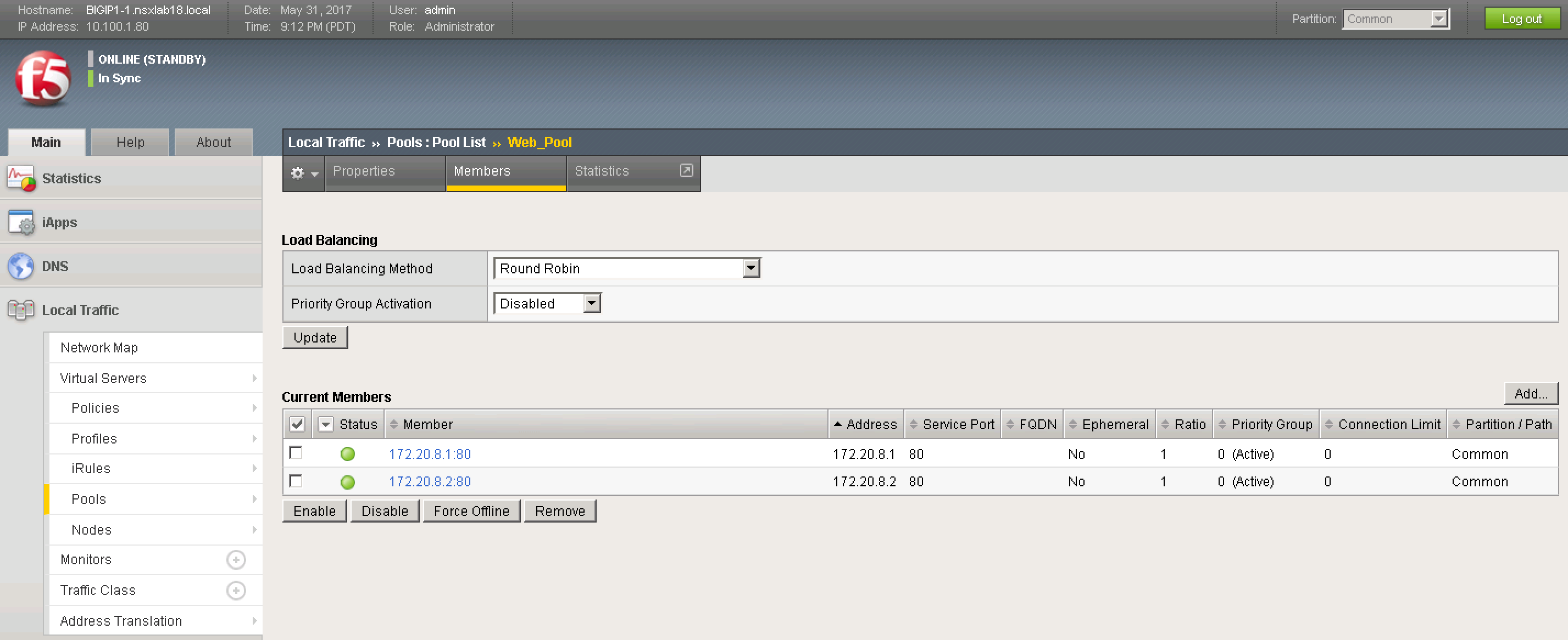
The F5 LTMs are monitoring the web servers that are part of a defined application pool. Figure 11 below shows this application pool as configured on site 1 LTMs.
![Figure 11: F5 LTM Pool Members]() Figure 11: F5 LTM Pool Members
Figure 11: F5 LTM Pool Members
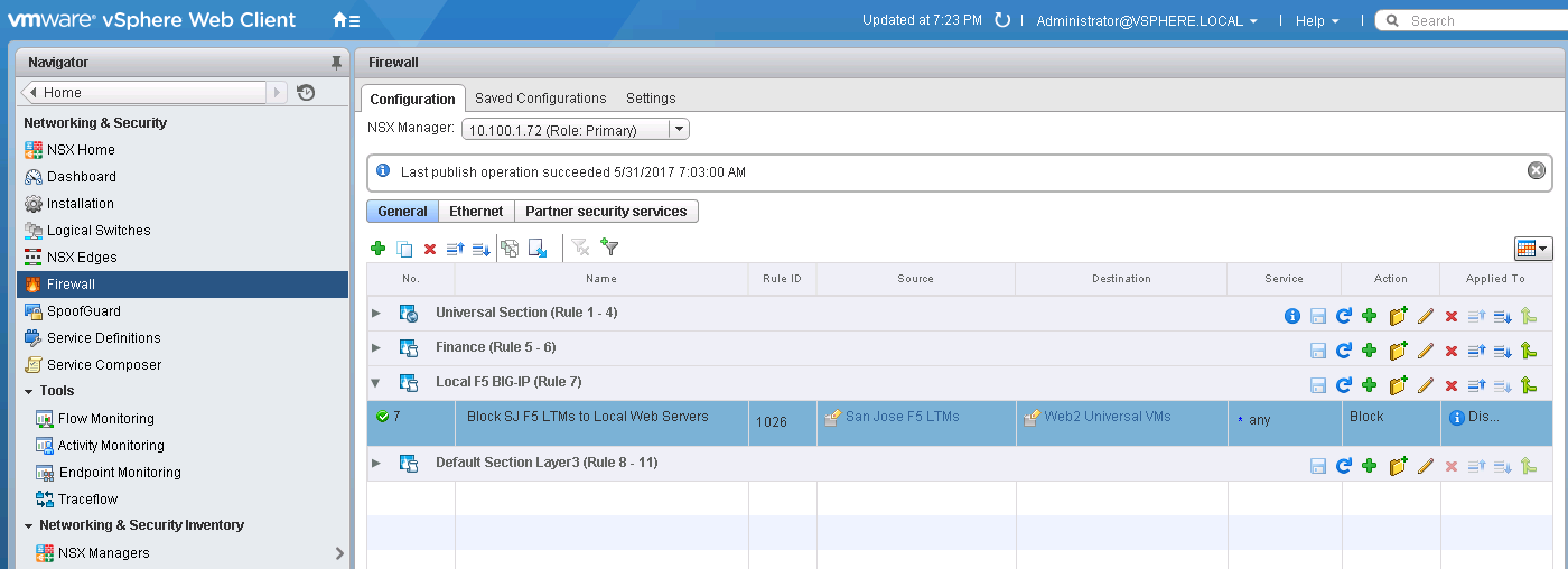
In NSX-V, using local firewall rules, the local LTMs at both sites are blocked from load balancing received requests to web servers that are sitting at the other site. An example of the firewall configuration for site 1 is shown below in Figure 12. Thus, in Figure 11, since the Web VM with IP address 172.20.8.2 is sitting in site 2, the status on the pool member is red. In this case the setup is Active-Active, and the F5 BIG-IP DNS will load balance across sites to the Web servers as specified by the load balancing method.
![Figure 12: NSX-V DFW Configuration at Site 1 to Block Site 2 LTMs]() Figure 12: NSX-V DFW Configuration at Site 1 to Block Site 2 LTMs
Figure 12: NSX-V DFW Configuration at Site 1 to Block Site 2 LTMs
If the Web VM at site 2 is vMotioned to site 1, the status of the respective pool member will turn green as shown below in Figure 13.
![Figure 13: F5 LTM Pool Members]() Figure 13: F5 LTM Pool Members
Figure 13: F5 LTM Pool Members
Now, if a DNS query is made, to any of the F5 BIG-IP DNS at either site, the External VIP IP address of site 1 (10.100.9.14) will always be returned as shown in Figure 14 below where 2 queries are made to the site 2 F5 BIG-IP DNS.
![Figure 14: Site 2 DNS Reply to First Query]() Figure 14: Site 2 DNS Reply to First Query
Figure 14: Site 2 DNS Reply to First Query
![Figure 15: Site 2 DNS Reply to Second Query]() Figure 15: Site 2 DNS Reply to Second Query
Figure 15: Site 2 DNS Reply to Second Query
As mentioned prior, there are several NSX-V with F5 BIG-IP DNS topologies that can be utilized for different use cases. In this post, I discussed how VMware NSX-V and F5 BIG-IP DNS can be used together for an Active/Active solution for web applications spanning multiple sites where site-local ingress/egress for the application is desired. In future posts, we’ll look at additional topologies and how deployment of such a solution can be further automated. For more information on multi-site solutions with NSX-V, check-out my prior blog posts here and take a look at the NSX-V Multi-site Options and Cross-VC NSX Design Guide. For additional information on F5 BIG-IP DNS check-out the F5 Networks website.
The post Multi-site Active-Active Solutions with NSX-V and F5 BIG-IP DNS appeared first on Network Virtualization.


 NET1949 VMware NSX for Docker, Containers & Mesos
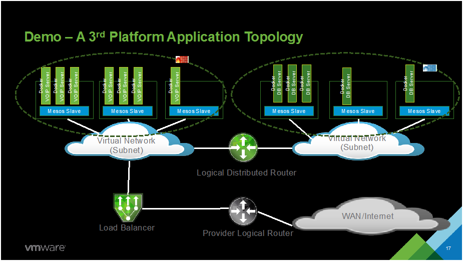


 Key requirements of the Software-Defined Branch solution are depicted in the diagram. With these, the branch can evolve to be more agile asset of the organization, adaptable and open to new innovations. In addition, these can lower capital and operating expenses compared to the traditional branch infrastructure by enabling a more streamlined operational IT model.


 In the